This chapter describes the main basic concepts of computer systems.
1.1 Introduction
The majority of electronics products (cellular phones, tablets, notebooks, radios, smart televisions, etc.) are currently implemented with microprocessors, memories and basic electronic circuits, named input/output interfaces, which perform the interaction with the humans. These basic electronic circuits compose the computer systems. So, this chapter aims to describe the fundamental concepts to understand these wonderful machines.
1.2 Numeral Systems (System of Numeration)
The law of numerical formation in a specific base (b) is given by ... dmd3d2d1d0.d1d2d3d-n ..., where dm and dn represent a specific digit of the considered numerical base, before and after the point, respectively, and m + 1 and n are the quantity of digits that define the number, before and after the point, respectively. In order to know how this number is given in the decimal base, we need to use Eq. ( ].
For instance, if m is equal to 9, the number has 10 digits before the point (integer part of the number), and if n is equal to 5, the number has 5 digits after the point (fractional part of the number). If there are ten digits before the point (d9 d0), the digit d9 is defined as the most significant digit (MSD), and if there are three digits after the point, d3 is defined as the least significant digit (LSD) [].
To exemplify, the number 12345.678 in the base 10 (decimal representation) can be represented by using Eq. ( ]:
In Eq. ( ].
Similarly, the value in the base 10 of the number 1111.01 in the base 2, i.e., (1111.01)2, is given by Eq. ( ]:
The numerical bases that are most commonly used in computer systems are the binary, hexadecimal, and BCD (binary-coded decimal) [].
1.2.1 Decimal Numeral System (Base 10)
It is the numeral system used by humans, which is composed of ten digits, named decimal digits: 0, 1, 2, ..., 9 [].
1.2.2 Binary Numeral System
The binary digits or bits are formed by the digits 0 and 1. They belong to the base 2 numeral system. This numeral system is commonly used in computer systems because it is capable of representing the digital electrical behavior of the transistors operating as a switch, i.e., open switch (cut-off region: deactivated condition, turn-off, etc.) and off switch (triode region: activated condition, turn-on, the transistor is saturated, etc.). Regarding the logic positive in digital electronics, the open-switch condition of the transistor is defined as zero logic or 0 logic and the off-switch condition of the transistor is defined as one logic or 1 logic. The 0 logic usually corresponds to the 0 volt (0 V), and the 1 logic corresponds to the 5.0 volts (5.0 V), 3.0 V, 1.2 V, etc., depending on the complementary metal-oxide semiconductor (CMOS) of integrated circuit (IC) technology adopted [].
The number of binary combinations generated by a bit is equal to 2 (2number of bits = 21 = 2), i.e., there are two possible binary combinations, which can be 0 logic or 1 logic, as illustrated in Table ].
Table 1.1
Number of binary combinations by using a bit
Binary combinations by using a bit | bit | Decimal value |
|---|
First binary combination | | 020 = 0 |
Second binary combination | | 121 = 1 |
The highest value of the binary combination that can be represented with one single bit is defined as the number of binary combinations subtracted by one, i.e., 2(number of bits 1) = 211 = 21 = 1, as indicated in Table ].
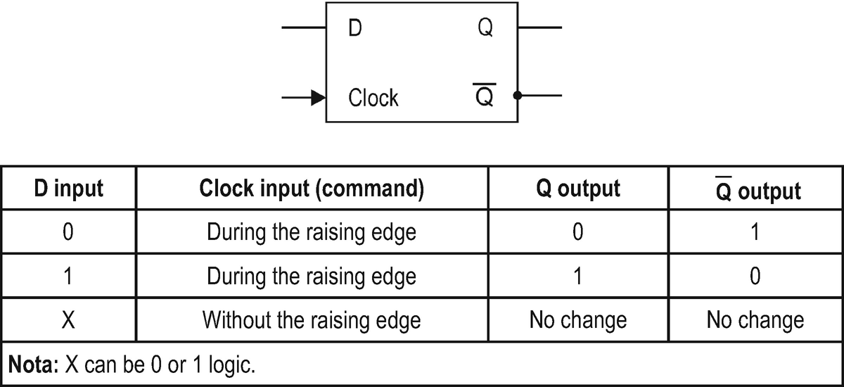
The synchronous D-type flip-flop (with clock input) is an example of a basic digital circuit which is responsible for storing a single bit, according to Fig. ].
Fig. 1.1
Electrical representation of the synchronous D-type flip-flop and its truth table
When a bit is defined in the input of a synchronous D-type flip-flop, it will be only copied and stored in the Q output when a rising edge (from 0 to 1 logic) is set in its clock input. The absence of an electrical signal (rising edge) in the clock input does not enable the copy and storage of the bit from the D input to the Q output, and consequently its Q output remains with the previous state. The minimum time of the clock pulse or the maximum frequency that a synchronous D-type flip-flop can operate is determined by the CMOS ICs technology used. The higher the frequency of the flip-flops, the higher the processing speed of computer systems [].
The numerical representation using 8 bits is defined as a byte. The number of possible binary combinations with 8 bits is 256 (2number of bits = 28), and the highest value of this numerical representation is 255 (2number of bits 1 = 281 = 2561), as shown in Table ].
Table 1.2
Possible binary combinations in an 8-bit binary presentation (byte)
Binary combinations in an 8-bit binary presentation (byte) | Byte D7D6D5D4D3D2D1D0 2726252423222120 | Decimal value |
|---|
First binary combination | 0 0 0 0 0 0 0 0 | 027 + 026 + 025 + 024 + 023 + 022 + 021 + 020 = 0 |
Second binary combination | 0 0 0 0 0 0 0 1 | 027 + 026 + 025 + 024 + 023 + 022 + 021 + 121 = 1 |
Third binary combination | 0 0 0 0 0 0 1 0 | 027 + 026 + 025 + 024 + 023 + 022 + 121 + 021 = 2 |
Fourth binary combination | 0 0 0 0 0 0 1 1 | 027 + 026 + 025 + 024 + 023 + 022 + 121 + 121 = 3 |
Fifth binary combination | 0 0 0 0 0 1 0 0 | 027 + 026 + 025 + 024 + 023 + 122 + 021 + 021 = 4 |
Sixth binary combination | 0 0 0 0 0 1 0 1 | 027 + 026 + 025 + 024 + 023 + 122 + 021 + 121 = 5 |
: | : | : |
Penultimate binary combination | 1 1 1 1 1 1 1 0 | 127 + 126 + 125 + 124 + 123 + 122 + 121 + 021 = 254 |
Last binary combination | 1 1 1 1 1 1 1 1 | 127 + 126 + 125 + 124 + 123 + 122 + 121 + 121 = 255 |

