Table of Contents
Chapter 1
x86 and x64
The x86 is little-endian architecture based on the Intel 8086 processor. For the purpose of our chapter, x86 is the 32-bit implementation of the Intel architecture (IA-32) as defined in the Intel Software Development Manual . Generally speaking, it can operate in two modes: real and protected . Real mode is the processor state when it is first powered on and only supports a 16-bit instruction set. Protected mode is the processor state supporting virtual memory, paging, and other features; it is the state in which modern operating systems execute. The 64-bit extension of the architecture is called x64 or x86-64. This chapter discusses the x86 architecture operating in protected mode.
x86 supports the concept of privilege separation through an abstraction called ring level . The processor supports four ring levels, numbered from 0 to 3. (Rings 1 and 2 are not commonly used so they are not discussed here.) Ring 0 is the highest privilege level and can modify all system settings. Ring 3 is the lowest privileged level and can only read/modify a subset of system settings. Hence, modern operating systems typically implement user/kernel privilege separation by having user-mode applications run in ring 3, and the kernel in ring 0. The ring level is encoded in the CS register and sometimes referred to as the current privilege level (CPL) in official documentation.
This chapter discusses the x86/IA-32 architecture as defined in the Intel 64 and IA - 32 Architectures Software Developer's Manual , Volumes 1 ( www.intel.com/content/www/us/en/processors/architectures-software-developer-manuals.html ).
Register Set and Data Types
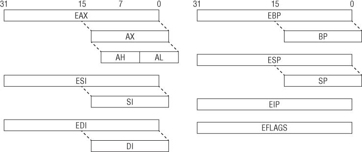
When operating in protected mode, the x86 architecture has eight 32-bit general-purpose registers (GPRs): EAX , EBX , ECX , EDX , EDI , ESI , EBP , and ESP . Some of them can be further divided into 8- and 16-bit registers. The instruction pointer is stored in the EIP register. The register set is illustrated in describes some of these GPRs and how they are used.

Some GPRs and Their Usage
| Register | Purpose |
| ECX | Counter in loops |
| ESI | Source in string/memory operations |
| EDI | Destination in string/memory operations |
| EBP | Base frame pointer |
| ESP | Stack pointer |
The common data types are as follows:
- Bytes 8 bits. Examples: AL , BL , CL
- Word 16 bits. Examples: AX , BX , CX
- Double word 32 bits. Examples: EAX , EBX , ECX
- Quad word 64 bits. While x86 does not have 64-bit GPRs, it can combine two registers, usually EDX:EAX , and treat them as 64-bit values in some scenarios. For example, the RDTSC instruction writes a 64-bit value to EDX:EAX .
The 32-bit EFLAGS register is used to store the status of arithmetic operations and other execution states (e.g., trap flag). For example, if the previous add operation resulted in a zero, the ZF flag will be set to 1. The flags in EFLAGS are primarily used to implement conditional branching.
In addition to the GPRs, EIP , and EFLAGS , there are also registers that control important low-level system mechanisms such as virtual memory, interrupts, and debugging. For example, CR0 controls whether paging is on or off, CR2 contains the linear address that caused a page fault, CR3 is the base address of a paging data structure, and CR4 controls the hardware virtualization settings. DR0 DR7 are used to set memory breakpoints. We will come back to these registers later in the System Mechanism section.
Note Although there are seven debug registers, the system allows only four memory breakpoints ( DR0 DR3 ). The remaining registers are used for status.
There are also model-specific registers (MSRs). As the name implies, these registers may vary between different processors by Intel and AMD. Each MSR is identified by name and a 32-bit number, and read/written to through the RDMSR/WRMSR instructions. They are accessible only to code running in ring 0 and typically used to store special counters and implement low-level functionality. For example, the SYSENTER instruction transfers execution to the address stored in the IA32_SYSENTER_EIP MSR (0x176), which is usually the operating system's system call handler. MSRs are discussed throughout the book as they come up.
Instruction Set
The x86 instruction set allows a high level of flexibility in terms of data movement between registers and memory. The movement can be classified into five general methods:
- Immediate to register
- Register to register
- Immediate to memory
- Register to memory and vice versa
- Memory to memory
The first four methods are supported by all modern architectures, but the last one is specific to x86. A classical RISC architecture like ARM can only read/write data from/to memory with load/store instructions ( LDR and STR , respectively); for example, a simple operation like incrementing a value in memory requires three instructions:
Read the data from memory to a register ( LDR ). Add one to the register ( ADD ). Write the register to memory ( STR ).
On x86, such an operation would require only one instruction (either INC or ADD ) because it can directly access memory. The MOVS instruction can read and write memory at the same time.
ARM
01: 1B 68 LDR R3, [R3]
; read the value at address R3
02: 5A 1C ADDS R2, R3, #1
; add 1 to it
03: 1A 60 STR R2, [R3]
; write updated value back to address R3
x86
01: FF 00 inc dword ptr [eax]
; directly increment value at address EAX
Another important characteristic is that x86 uses variable-length instruction size: the instruction length can range from 1 to 15 bytes. On ARM, instructions are either 2 or 4 bytes in length.
Syntax
Depending on the assembler/disassembler, there are two syntax notations for x86 assembly code, Intel and AT&T:
Intel
mov ecx, AABBCCDDh
mov ecx, [eax]
mov ecx, eax
AT&T
movl $0xAABBCCDD, %ecx
movl (%eax), %ecx
movl %eax, %ecx
It is important to note that these are the same instructions but written differently. There are several differences between Intel and AT&T notation, but the most notable ones are as follows:
- AT&T prefixes the register with % , and immediates with $ . Intel does not do this.
- AT&T adds a prefix to the instruction to indicate operation width. For example, MOVL (long), MOVB (byte), etc. Intel does not do this.
- AT&T puts the source operand before the destination. Intel reverses the order.
Disassemblers/assemblers and other reverse-engineering tools (IDA Pro, OllyDbg, MASM, etc.) on Windows typically use Intel notation, whereas those on UNIX frequently follow AT&T notation (GCC). In practice, Intel notation is the dominant form and is used throughout this book.
Data Movement
Instructions operate on values that come from registers or main memory. The most common instruction for moving data is MOV . The simplest usage is to move a register or immediate to register. For example:
01: BE 3F 00 0F 00 mov esi, 0F003Fh ; set ESI = 0xF003
02: 8B F1 mov esi, ecx ; set ESI = ECX
The next common usage is to move data to/from memory. Similar to other assembly language conventions, x86 uses square brackets ( [] ) to indicate memory access. (The only exception to this is the LEA instruction, which uses [] but does not actually reference memory.) Memory access can be specified in several different ways, so we will begin with the simplest case:
Assembly
01: C7 00 01 00 00+ mov dword ptr [eax], 1
; set the memory at address EAX to 1
Next page


