AN INTRODUCTION TO
THEORETICAL
AND
COMPUTATIONAL
AERODYNAMICS
J ACK M ORAN University of Minnesota DOVER PUBLICATIONS, INC. Mineola, New York
Copyright Copyright 1984 by Jack Moran All rights reserved.
Bibliographical Note This Dover edition, first published in 2003, is an unabridged republication of the work originally published by John Wiley & Sons, New York, in 1984.
Library of Congress Cataloging-in-Publication Data Moran, Jack. An introduction to theoretical and computational aerodynamics / Jack Moran. cm. cm.
Originally published: New York : Wiley, c1984. Includes bibliographical references and index. ISBN-13: 978-0-486-42879-6 (pbk.) ISBN-10: 0-486-4287-6 (pbk.) 1. Aerodynamics. I. Title.
TL570.M587 2003 629.1323dc21 2003043969 Manufactured in the United States by Courier Corporation 42879602 www.doverpublications.com Dedicated to WILLIAM R. SEARS Director of the Graduate School of Aeronautical Engineering at Cornell University & WILLIAM H. THOMSEN My Father-in-Law Without whose help I never would have had the chance to learn what I have PREFACE This textbook on aerodynamics is based on courses I have given at the University of Minnesota for the past several years. Perhaps the most useful way of describing what is and is not in the text is to outline the courses and their prerequisites. (up through Rankine ovals) is actually a review for them. are used in our students second one-quarter course in fluid mechanics, which deals with viscous flows.
They are not the sole basis for that course, since they lack any discussion of pipe flows. However, I find most fluid mechanics texts do a good job on that topic and saw no need to compete with them here. The material in is a departure from existing texts, but one that we feel is necessary if our students are to move smoothly into the aerospace industry on their graduation. The specific programs developed in depth are sufficiently close to those used in practice to ease this transition. In my opinion, the emphasis on computer usage also reinforces otherwise esoteric concepts like source and vortex flows. No prior knowledge of computational methods is required, but students are expected to be able to read and make functional changes in FORTRAN programs.
The theory behind the methods is not presented rigorously but is intended to be detailed enough that the programs are not just black boxes. introduces the student to the computation of transonic flows. Although it touches briefly on sub- and supersonic flows, it really should be (and is, at the University of Minnesota) preceded by a full one-quarter course on compressible fluid mechanics, which in turn requires a prior course in thermodynamics. The text includes listings of 14 FORTRAN computer programs that implement methods developed in the text. For the most part, these should run on any FORTRAN compiler. Few of the programs even use the IF-THEN-ELSE construction; they are largely standard FORTRAN IV.
Exceptions are the printer-plotting routines PLOTXY and CONTUR, which may have to be revised or discarded. Also, program TSDE in calls subroutines GETPF and REPLACE, available on the University of Minnesota system, which attach and replace, respectively, a named data file. Finally, most of the programs make liberal use of the Cyber-FORTRAN commands READ and PRINT for interactive input and output. References are made in to programs with graphic input and output capabilities on a microcomputer. For further information on this software, contact the author, who will also be glad to receive suggestions and comments on the text. Jack MoranMinneapolis, MinnesotaJune 1983CONTENTS A N INTRODUCTION TO THEORETICAL
AND
COMPUTATIONAL
AERODYNAMICS CHAPTER 1WINGS Most of this book is about the aerodynamics of wings.
Therefore, we start by looking at wings, what they do, and how they do it. 1.1. FUNCTION The main purpose of a wing is to provide a lift force, the force that gets the airplane off the ground, raises it to an efficient and safe cruising altitude, lets it maneuver about, and allows a safe landing. The same results can be obtained by pointing a rocket or other engine in the right direction, and that, in fact, is how you fly in the absence of an atmosphere. However, when an atmosphere is available, a lot of energy can be saved by using wings. The wing acts as a thrust amplifier, giving you a lifting force many times the force it takes to keep you going.
To make this precise, consider an airplane in straight and level flight at speed V, as shown in . However, shouldnt the propulsion-system specialist also be held accountable for the drag on the exterior of the engine nacelle? With a little imagination, you can visualize the pain various definitions of thrust could cause different members of the design team. 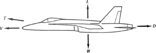 FIG. 1.1. Balance of forces on an airplane in straight and level constant-speed flight.
  FIG. 1.2. 1.2.
Control volume for analyzing the drag of a propulsion system. Once the thrust is defined, the aerodynamic forces on the remaining surfaces of the aircraft are resolved into components along and parallel to the direction of flight. Lift is the component perpendicular to the velocity vector V, whereas drag is the component along (but opposite to) V. For flight at constant speed and altitude, the propulsive system thrust is in rough balance with the drag, and the lift with the weight. Of course, to change direction, the lift must exceed the weight, and the thrust must exceed the drag when you need to accelerate. However, what I meant when I called the wing a thrust amplifier is that its lift, which must at least equal the airplanes weight in order for it to get off the ground, can be many times as large as its drag, which must be overcome by the engines thrust.
This can be seen from , the lift to drag ratio of the complete airplane is considerably less than that of the wing alone, but it is still more than eight for fighters and about twice that for transports. Thus, for example, the C5A lifts over 750,000 lb with four 41,000-lb thrust engines. 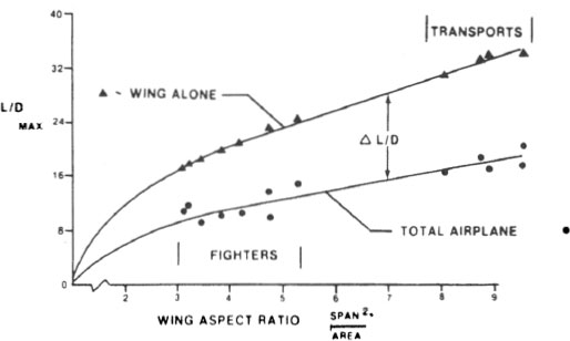 FIG. 1.3. Maximum lift to drag ratios for fighters and transports in subsonic flight.
 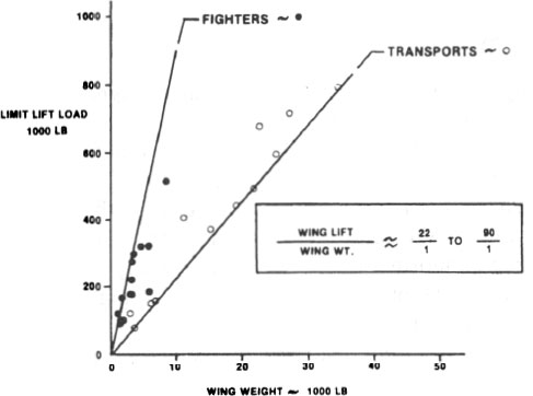 FIG. 1.4. 1.4.
Maximum lift/weight ratio for fighters and transports in subsonic flight. Copyright AIAA; from The AIAA Evolution of Aircraft Wing Design Symposium, 1980 []. Lift and drag are not the only parameters of interest to the aerodynamicist. He or she must also know where the lift acts, what is called the center of pressure of the wing. To fly straight and level, for example, the airplane must be in equilibrium with respect to the moments about its mass center of the forces acting on it; see most aircraft use the wings to store fuel and also the landing gear. 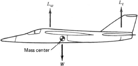 FIG. 1.5. 1.5.
Balance of moments about mass center on a trimmed aircraft. 1.2. GEOMETRY Having briefly outlined the objectives of wing design, let us now look at the geometric variables at the designers disposal. The first is
Next page





 FIG. 1.1. Balance of forces on an airplane in straight and level constant-speed flight.
  FIG. 1.2. 1.2.
 FIG. 1.3. Maximum lift to drag ratios for fighters and transports in subsonic flight.
  FIG. 1.4. 1.4.
 FIG. 1.5. 1.5.