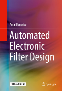
Banerjee - Automated Electronic Filter Design
Here you can read online Banerjee - Automated Electronic Filter Design full text of the book (entire story) in english for free. Download pdf and epub, get meaning, cover and reviews about this ebook. City: Cham, year: 2017, publisher: Springer International Publishing, genre: Home and family. Description of the work, (preface) as well as reviews are available. Best literature library LitArk.com created for fans of good reading and offers a wide selection of genres:
Romance novel
Science fiction
Adventure
Detective
Science
History
Home and family
Prose
Art
Politics
Computer
Non-fiction
Religion
Business
Children
Humor
Choose a favorite category and find really read worthwhile books. Enjoy immersion in the world of imagination, feel the emotions of the characters or learn something new for yourself, make an fascinating discovery.
- Book:Automated Electronic Filter Design
- Author:
- Publisher:Springer International Publishing
- Genre:
- Year:2017
- City:Cham
- Rating:4 / 5
- Favourites:Add to favourites
- Your mark:
- 80
- 1
- 2
- 3
- 4
- 5
Automated Electronic Filter Design: summary, description and annotation
We offer to read an annotation, description, summary or preface (depends on what the author of the book "Automated Electronic Filter Design" wrote himself). If you haven't found the necessary information about the book — write in the comments, we will try to find it.
Automated Electronic Filter Design — read online for free the complete book (whole text) full work
Below is the text of the book, divided by pages. System saving the place of the last page read, allows you to conveniently read the book "Automated Electronic Filter Design" online for free, without having to search again every time where you left off. Put a bookmark, and you can go to the page where you finished reading at any time.
Font size:
Interval:
Bookmark:
- Basic loop equations are derived from Kirchhoffs current/voltage laws (KCL/KVL). These loop equations are differential equations, sometimes nonlinear. Typically, these differential equations are converted to more tractable algebraic equations, using Laplace transforms, effectively going from the time to frequency domain.
- In the filter transfer function H ( s ), the Laplace transform of the unit impulse response of the filter is obtained by evaluating H ( s ) at s = jw (in general, s = a + jw and s = jw represent a pure sinusoidal input). For calculation purposes, it is the ratio of the output to the input voltage in the frequency domain. The transfer function is almost always in a denominator-numerator polynomial form. The goal is to determine the roots of these two polynomials in the complex s -plane to obtain the poles and zeros. Poles and zeros are, respectively, the roots of the denominator and numerator polynomials. Only poles in the left half of the complex s -plane guarantee filter stability and need to be complex conjugates of each other to ensure real-valued coefficients in the differential equations representing the filter. Most importantly, for the generic case, the pole (and zero) values are analytical expressions involving the capacitors, inductors, and resistors to be used in the filter. Both the denominator and numerator polynomials need to be factorized to extract the zeros and poles of the transfer function. Sometimes, instead of using the transfer function, expressions for the filter insertion loss or loss magnitude versus frequency are used [], but that scheme involves first evaluating the loss expression in terms of the filter component values and then using a judicious combination of heuristics, ladder network, and precalculated table values.
- The most difficult step is to use the values of the poles and zeros evaluated previously and to determine values of each of the resistive and reactive components (capacitors, inductors) in the filter circuit. In the generic case, using the analytical expressions for the values of poles and zeros in combination with the predefined numerical values of design specifications (cutoff frequency, pass/stop band ripple, etc.) is an extremely complicated, manual, and thus error-prone/time-consuming/trial-and-error process. The designer can also utilize the causality and stability conditions and set resistor values to 1 to aid/simplify this calculation. Clearly, this step is feasible for low-order filters only.


- Eliminate all manual and/or time-consuming/error-prone calculation steps.
- It must be possible to seamlessly verify that the final design satisfies specifications with a proven technique or tool.
Font size:
Interval:
Bookmark:
Similar books «Automated Electronic Filter Design»
Look at similar books to Automated Electronic Filter Design. We have selected literature similar in name and meaning in the hope of providing readers with more options to find new, interesting, not yet read works.
Discussion, reviews of the book Automated Electronic Filter Design and just readers' own opinions. Leave your comments, write what you think about the work, its meaning or the main characters. Specify what exactly you liked and what you didn't like, and why you think so.


