Different Methods for Light Trapping
Light-trapping schemes can be implemented at both the front and rear surfaces of the solar cell . Several approaches had been adopted, which include randomly roughened surfaces [] to enhance the photo-generation due to a higher degree of scattering and reflection. However, a careful optimization of the periodicity and the height of the gratings is required, which increases process complexity and costs.
On the other hand, utilizing a simple one-dimensional distributed Bragg reflector for rear-surface light trapping appears to be an attractive option as well. Previous studies had included using at least one insulating or moderately conducting layer such as combinations of Si/Si3N4 or Si/SiO2 stacks []. Considering the ease and merits of integrating a DBR scheme at the rear of a thin silicon wafer for light trapping, the subsequent sections focus on the proper design of a DBR-based light-trapping scheme.
Design Methodology of a Distributed Bragg Reflector
Similar to a semiconductor with a defined bandgap within which no electronic states can exist, an analogous situation is observed for photons in a distributed Bragg reflector (equivalently a one-dimensional photonic crystal [. If films with a periodically varying dielectric function (or index of refraction) are stacked together, the reflections and refractions of light from the various interfaces can create photonic bandgaps , which will forbid photon propagation in certain directions for a certain (designed) photon wavelength 0 within a certain bandwidth 0.
Fig. 2
Schematic of a one-dimensional photonic crystal (distributed Bragg reflector, DBR). The DBR consists of several DBR unit blocks. Each DBR unit block consists of alternating layers of two materials with different dielectric constants, with a period a (From Ref. [])
To realize the DBR, periodic stacks of two layers (DBR unit blocks) with different refractive indices n 1 and n 2 are chosen, whereby n 1 > n 2. For the DBR unit block, the thickness of the individual layers d 1 and d 2 is typically chosen to satisfy a quarter-wavelength stack at the target peak reflectance wavelength 0 [] as:
where d is a function of the target peak reflectance wavelength 0 and the refractive index n of that layer at that wavelength. The objective of using a quarter-wavelength stack is to achieve quarter-wavelength optical thickness for the individual layers, so that for a DBR with multiple stacks of periodic DBR unit blocks, only wavelengths within the designed peak reflectivity regions interfere constructively, while the rest interfere destructively to give lower or zero reflectance. The overall optical reflectance at the target wavelength and its bandwidth is thus highly enhanced, so that the designed distributed Bragg reflector acts as a mirror.
It is also of relevance to find out the wavelength range (bandwidth) around the target peak reflectance wavelength for which high optical reflectance is expected. From experimental and theoretical analysis, the bandwidth can be approximated via the gapmidgap ratio 0/0 []:
where 0 denotes the bandwidth at the target peak reflectance wavelength 0. The bandwidth 0 defines the photonic gap between the first two bands of a quarter-wavelength stack, analogous to a bandgap in a semiconductor material. If we define a refractive index contrast R such that R = n 1/ n 2, the above equation can be rewritten as:
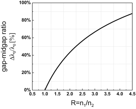
With an increasing refractive index contrast, the gapmidgap ratio 0/0 increases as evident in Fig. , indicating a wider reflection bandwidth 0 for the DBR unit block.
Fig. 3
Gapmidgap ratio 0/0 of a DBR unit block as a function of the refractive index contrast R = n 1/ n 2
The optical reflectance of a DBR can be expressed as []:
where n 0 , n 1 , n 2, and n s are the refractive indices of the ambient, of Bragg material 1, of Bragg material 2, and of the substrate, respectively, and N is the number of DBR unit blocks making up the DBR. From Fig. shows that a hypothetical DBR with a refractive index contrast of 1.5 would require 8 DBR unit blocks to approach unity reflection, whereas a DBR with a refractive index contrast of 3.5 would only need three DBR unit blocks. Thus, when considering DBRs, it is logical to utilize materials with a high refractive index contrast in order to reduce the number of DBR unit blocks required, as well as to benefit from a wider reflection bandwidth.


