Black & Decker Corporation (Towson Md.) - Wiring diagrams : current with 2011-2013 electrical codes
Here you can read online Black & Decker Corporation (Towson Md.) - Wiring diagrams : current with 2011-2013 electrical codes full text of the book (entire story) in english for free. Download pdf and epub, get meaning, cover and reviews about this ebook. City: Minneapolis, Minn, year: 2013, publisher: Creative Pub. International, genre: Home and family. Description of the work, (preface) as well as reviews are available. Best literature library LitArk.com created for fans of good reading and offers a wide selection of genres:
Romance novel
Science fiction
Adventure
Detective
Science
History
Home and family
Prose
Art
Politics
Computer
Non-fiction
Religion
Business
Children
Humor
Choose a favorite category and find really read worthwhile books. Enjoy immersion in the world of imagination, feel the emotions of the characters or learn something new for yourself, make an fascinating discovery.

- Book:Wiring diagrams : current with 2011-2013 electrical codes
- Author:
- Publisher:Creative Pub. International
- Genre:
- Year:2013
- City:Minneapolis, Minn
- Rating:5 / 5
- Favourites:Add to favourites
- Your mark:
Wiring diagrams : current with 2011-2013 electrical codes: summary, description and annotation
We offer to read an annotation, description, summary or preface (depends on what the author of the book "Wiring diagrams : current with 2011-2013 electrical codes" wrote himself). If you haven't found the necessary information about the book — write in the comments, we will try to find it.
Black & Decker Corporation (Towson Md.): author's other books
Who wrote Wiring diagrams : current with 2011-2013 electrical codes? Find out the surname, the name of the author of the book and a list of all author's works by series.
Wiring diagrams : current with 2011-2013 electrical codes — read online for free the complete book (whole text) full work
Below is the text of the book, divided by pages. System saving the place of the last page read, allows you to conveniently read the book "Wiring diagrams : current with 2011-2013 electrical codes" online for free, without having to search again every time where you left off. Put a bookmark, and you can go to the page where you finished reading at any time.
Font size:
Interval:
Bookmark:

Current with 2011-2013
Electrical Codes


T he arrangement of switches and appliances along an electrical circuit differs for every project. This means that the configuration of wires inside an electrical box can vary greatly, even when fixtures are identical.
The circuit maps on the following pages show the most common wiring variations for typical electrical devices. Most new wiring you install will match one or more of the maps shown. Find the maps that match your situation and use them to plan your circuit layouts.
The 120-volt circuits shown on the following pages are wired for 15 amps using 14-gauge wire and receptacles rated at 15 amps. If you are installing a 20-amp circuit, substitute 12-gauge cables and use receptacles rated for 20 amps.
In configurations where a white wire serves as a hot wire instead of a neutral, both ends of the wire are coded with black tape to identify it as hot. In addition, each of the circuit maps shows a box grounding screw. This grounding screw is required in all metal boxes, but plastic electrical boxes do not need to be grounded.
Note: For clarity, all grounding conductors in the circuit maps are colored green. In practice, the grounding wires inside sheathed cables usually are bare copper.
 Common Household Circuits
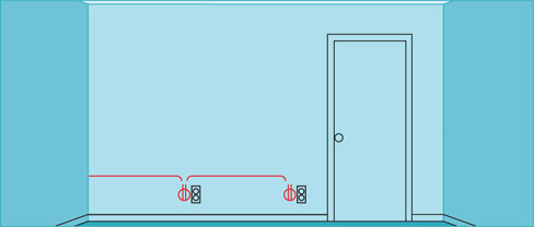
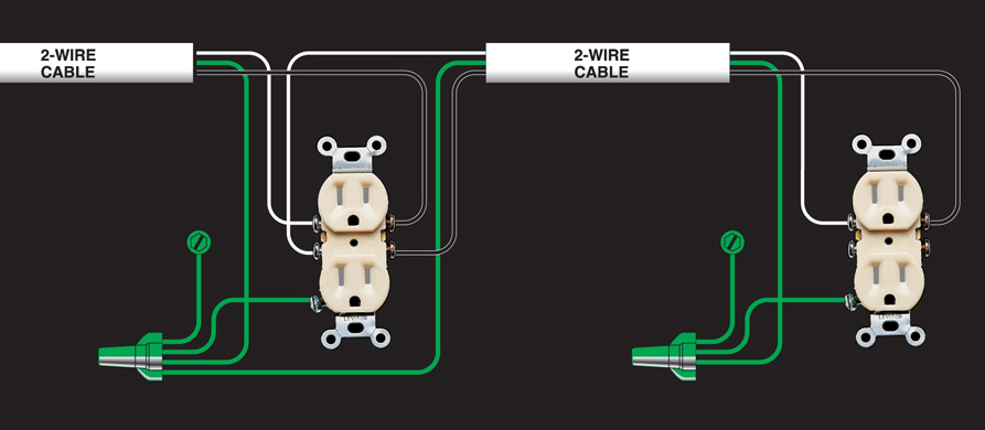
Use this layout to link any number of duplex receptacles in a basic lighting/receptacle circuit. The last receptacle in the cable run is connected like the receptacle shown at the right side of the circuit map below. All other receptacles are wired like the receptacle shown on the left side. Requires two-wire cables.
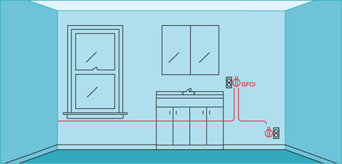
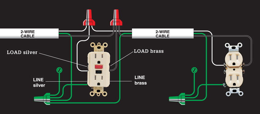
Use this layout when receptacles are within 6 ft. of a water source, like those in kitchens and bathrooms. To prevent nuisance tripping caused by normal power surges, GFCIs should be connected only at the line screw terminal so they protect a single location, not the fixtures on the load side of the circuit. Requires two-wire cables. Where a GFCI must protect other fixtures, use circuit map .
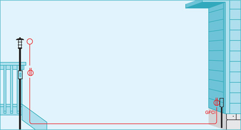
In some locations, such as an outdoor circuit, it is a good idea to connect a GFCI receptacle so it also provides shock protection to the wires and fixtures that continue to the end of the circuit. Wires from the power source are connected to the line screw terminals; outgoing wires are connected to load screws. Requires two-wire cables.
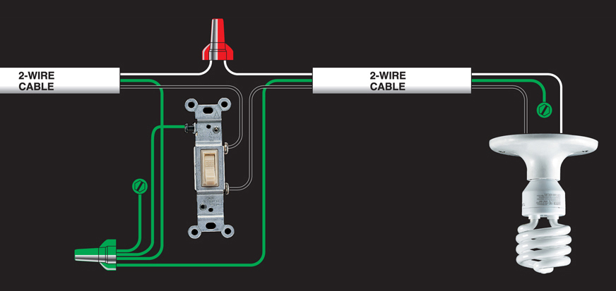
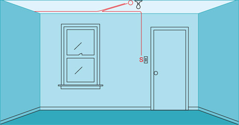
Use this layout for light fixtures in basic lighting/ receptacle circuits throughout the home. It is often used as an extension to a series of receptacles (circuit map ). Requires two-wire cables.
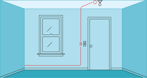
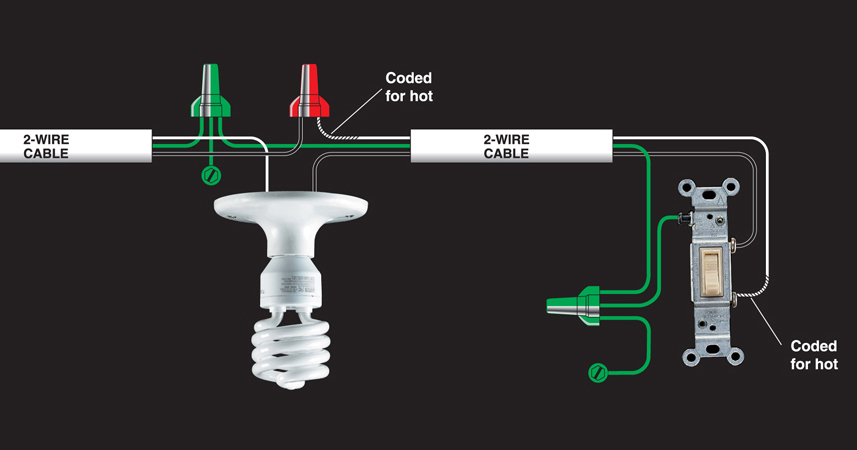
Use this layout, sometimes called a switch loop, where it is more practical to locate a switch at the end of the cable run. In the last length of cable, both insulated wires are hot; the white wire is tagged with black tape at both ends to indicate it is hot. Requires two-wire cables.
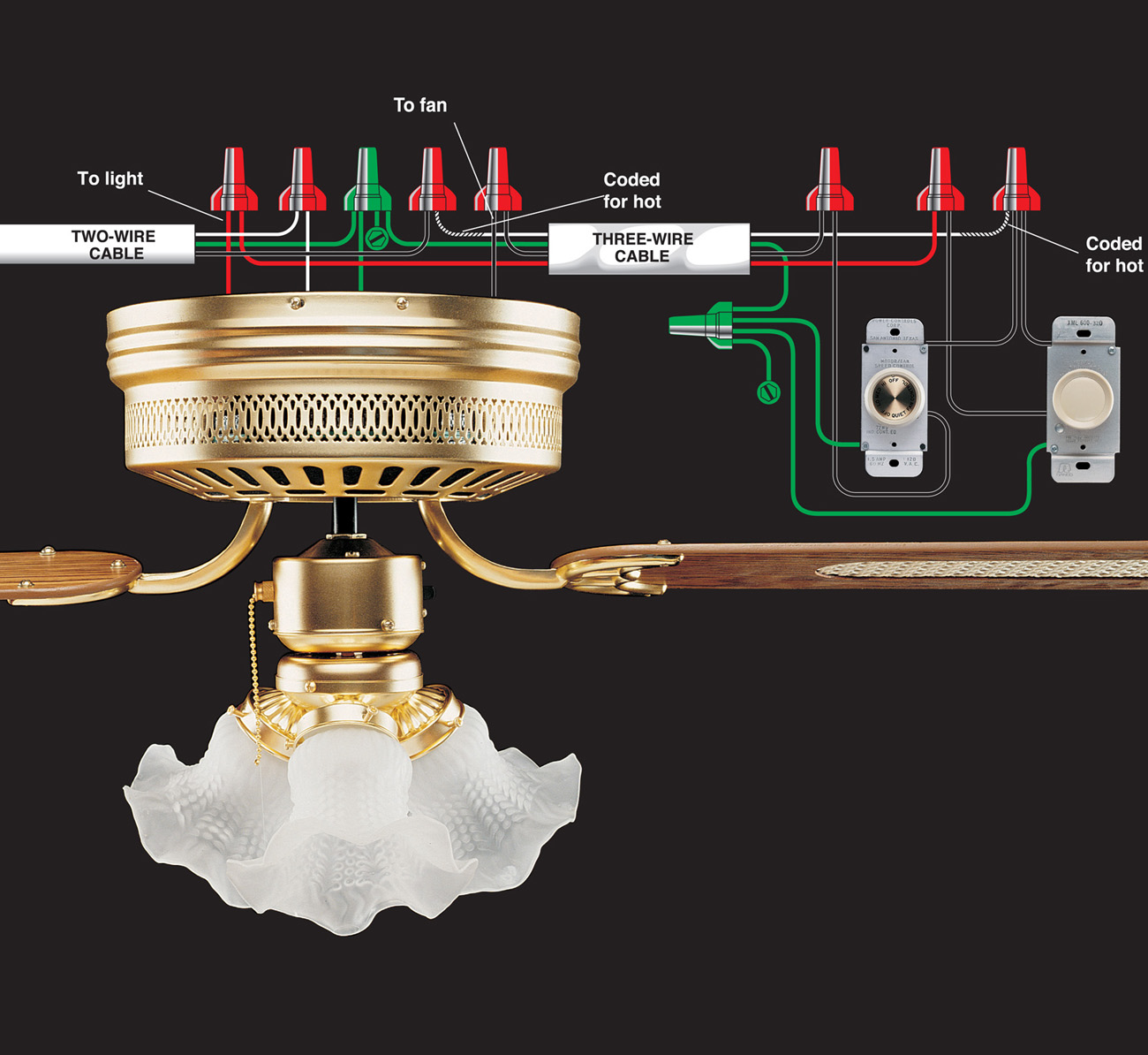
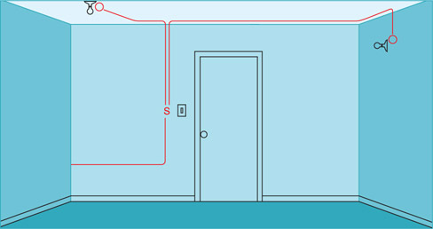
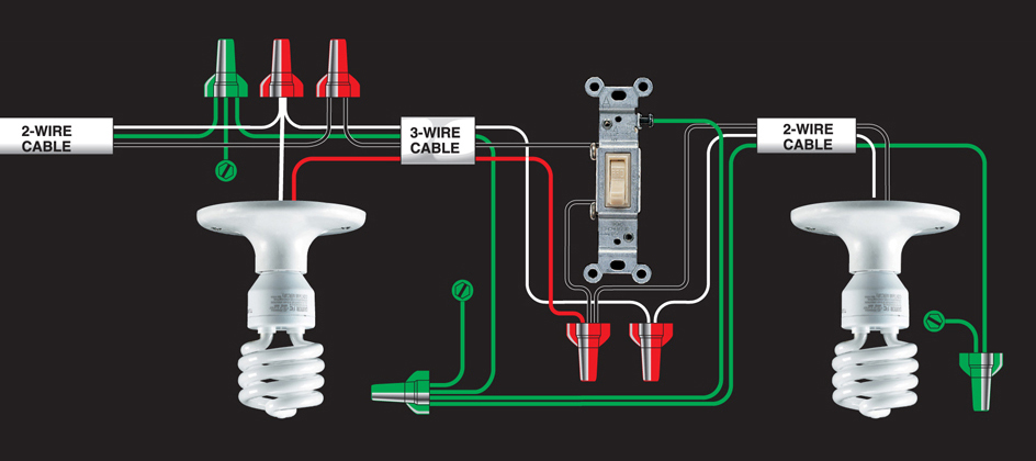
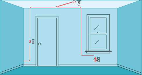
Use this layout when you need to control two fixtures from one single-pole switch and the switch is between the two lights in the cable run. Power feeds to one of the lights. Requires two-wire and three-wire cables.
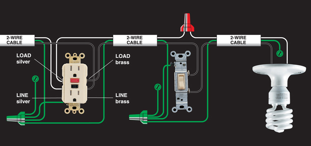
Use this layout to continue a circuit past a switched light fixture to one or more duplex receptacles. To add multiple receptacles to the circuit, see circuit map . Requires two-wire and three-wire cables.
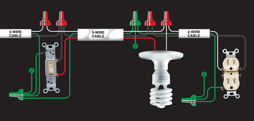
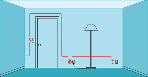
This layout lets you use a wall switch to control a lamp plugged into a wall receptacle. This configuration is required by code for any room that does not have a switch-controlled ceiling fixture. Only the bottom half of the first receptacle is controlled by the wall switch; the top half of the receptacle and all additional receptacles on the circuit are always hot. Requires two-wire and three-wire cables.
Font size:
Interval:
Bookmark:
Similar books «Wiring diagrams : current with 2011-2013 electrical codes»
Look at similar books to Wiring diagrams : current with 2011-2013 electrical codes. We have selected literature similar in name and meaning in the hope of providing readers with more options to find new, interesting, not yet read works.
Discussion, reviews of the book Wiring diagrams : current with 2011-2013 electrical codes and just readers' own opinions. Leave your comments, write what you think about the work, its meaning or the main characters. Specify what exactly you liked and what you didn't like, and why you think so.