1.1 General Concept of Creep
Historically, about a century ago, Andrade was among the first, if not the first, to pioneer and systematically study the concept of creep in metals. He called it a viscous flow in metals and indicated: that for a lead wire, loaded well beyond the elastic limit, the extension, after some time, becomes proportional to the time, or the flow becomes viscous in character. The rate of this viscous flow varies with the load. The method adapted to measure creep is to load a wire (or rod) axially and measure the extension with time at a constant stress. However, one must apply a constant load, maintained at constant temperature, and record the stain over a certain period of time. Modern, universal testing machines are commercially available and provide:
- (i)
Load measurement and control;
- (ii)
Extension measurement and control;
- (iii)
Time measurement;
- (iv)
Temperature measurement and control facilities;
- (v)
A chamber for controlled environmental and test conditions;
- (vi)
A computer for data acquisition and control; and
- (vii)
A testing apparatus equipped with grips, preventing slippage and excessive stress.
Andrade also classified creep. Creep occurs in three stages: primary creep (stage I); secondary creep (stage II); and tertiary creep (stage III). Stage I occurs at the beginning of a creep test. This creep is mostly characterized as transient creep , which does not occur at a steady rate. Resistance to creep increases until stage II is reached. In stage II, the rate of creep becomes steady or almost steady. This stage is also known as steady-state creep. In stage III, the creep rate begins to accelerate as the cross-sectional area of the specimen decreases due to necking or until internal voiding decreases the effective area of the specimen. If the test is allowed to proceed, fracture will occur, often referred to as rupture .
The first relations expressing extension under constant stress were formulated based on Andrades results from the extension of lead (Pb) wires, given as:
where l is the length at time t . l 0 is about the original constant length, expresses creep at a rate diminishing rapidly with time, hence its term as transient or creep. The creeping portion which proceeds at a constant rate (steady-state creep) is also known as being quasi-viscous creep or creep.
Creep curves are stress- and temperature-dependent, thus the three parameters that determine creep rate: time, temperature and stress, may be expressed by:
Temperature is an important parameter of creep in general and especially in ceramics. Since most ceramics are intended for high-temperature applications, guidelines are essential for understanding the limitations, if appreciable creep deformation is to be eliminated. Commonly, ceramics at high temperatures are ductile . For ceramics with low-temperature ductility, creep may occur at ~0.5 T m or may even set in at lower temperatures. The homologous temperature, defined in terms of the melting point, T m, serves as an efficient demarcation point between low-temperature and high-temperature creep, given as:
T is a relevant temperature of application and expressed (together with T m) on the absolute scale. Low-temperature creep below ~0.5 T m is considered to be governed by a nondiffusion-controlled mechanism, whereas high-temperature creep, above 0.5 T m, is diffusion controlled. Stress (load), time and temperature act simultaneously, determining the creep rate as expressed in Eq. (). When resistance to creep in ceramics is an essential prerequisite in high-temperature applications (preventing the risk of creep failure during their lifetime ) high T m ceramics are advisable. Some ceramics with very high melting points are: MgO (2798 C), Al2O3 (2050 C) and SiC, that will be discussed later in this book.
In order to eliminate grain boundary creep and grain boundary sliding , single-crystal ceramics are suggested for practical use in many applications, such as turbine blades, etc. In the next section, some basic relations are presented.
1.2 Basic Concepts
Most of the many equations describing creep given in the literature follow in the wake of Andrades empirical concept that one may express the variation of strain over time as:
which is equivalent to Eq. () may be expressed as:
Equation (), one obtains:
which is creep and represents a stationary state. Differentiating Eqs. (), respectively:
and the creep rate from Eq. () is:
Clearly, the last term in Eq. () in the second term.
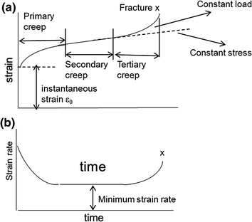
Figure is a schematic creep curve illustrating a constant load creep curve, and the constant stress curve is shown by the dashed line extension of the secondary creep .
Fig. 1.1
a A schematic creep curve along the lines of Andrade showing three stages of creep and an instantaneous elongation on application of load . A constant stress curve is incorporated in the overall illustration, indicated by the dashed line extension; b Schematic strain rate plot versus time; Pelleg, Mechanical Properties of Materials , Springer, 2013
All three stages of the conventional creep curve are shown in Fig. b. One can see from this illustration that, in the primary creep, the creep rate is continuously decreasing (hence its name transient creep ), while, in the secondary creep, the rate is constant (hence its name steady-state creep) and finally, in the tertiary creep , the creep rate is accelerating (hence it is also known as accelerated creep up to fracture. The constant creep rate is the minimum creep rate, which is an important design parameter and its magnitude is temperature- and stress-dependent. Two criteria of the minimum creep rate are commonly applied to alloys: (a) the stress needed to produce a creep rate of 0.1 103%/h (or 1% in 1 104 h) and (b) the stress needed to produce a creep rate of 0.1 104 %/h, namely 1% in 100 103 h, which is about 11.5 years. Criterion (a) is used for turbine blades, while (b) is usually applied to steam turbines.











![Joshua Backfield [Joshua Backfield] - Becoming Functional](/uploads/posts/book/120483/thumbs/joshua-backfield-joshua-backfield-becoming.jpg)