Springer International Publishing Switzerland 2017
Brock J. LaMeres Introduction to Logic Circuits & Logic Design with VHDL 10.1007/978-3-319-34195-8_1
1. Introduction: Analog vs. Digital
We often hear that we live in a digital age. This refers to the massive adoption of computer systems within every aspect of our lives from smart phones to automobiles to household appliances. This statement also refers to the transformation that has occurred to our telecommunications infrastructure that now transmits voice, video, and data using 1s and 0s. There are a variety of reasons that digital systems have become so prevalent in our lives. In order to understand these reasons, it is good to start with an understanding of what a digital system is and how it compares to its counterpart, the analog system. The goal of this chapter is to provide an understanding of the basic principles of analog and digital systems.
Learning Outcomes After completing this chapter, you will be able to:
- 1.1
Describe the fundamental differences between analog and digital systems.
- 1.2
Describe the advantages of digital systems compared to analog systems.
1.1 Differences Between Analog and Digital Systems
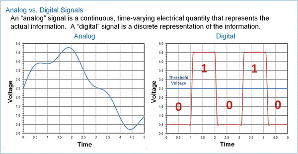
Lets begin by looking at signaling. In electrical systems, signals represent information that is transmitted between devices using an electrical quantity (voltage or current). An analog signal is defined as a continuous, time-varying quantity that corresponds directly to the information it represents. An example of this would be a barometric pressure sensor that outputs an electrical voltage corresponding to the pressure being measured. As the pressure goes up, so does the voltage. While the range of the input (pressure) and output (voltage) will have different spans, there is a direct mapping between the pressure and voltage. Another example would be sound striking a traditional analog microphone. Sound is a pressure wave that travels through a medium such as air. As the pressure wave strikes the diaphragm in the microphone, the diaphragm moves back and forth. Through the process of inductive coupling, this movement is converted to an electric current. The characteristics of the current signal produced (e.g., frequency and magnitude) correspond directly to the characteristics of the incoming sound wave. The current can travel down a wire and go through another system that works in the opposite manner by inductively coupling the current onto another diaphragm, which in turn moves back and forth forming a pressure wave and thus sound (i.e., a speaker). In both of these examples, the electrical signal represents the actual information that is being transmitted and is considered analog . Analog signals can be represented mathematically as a function with respect to time.
In digital signaling the electrical signal itself is not directly the information it represents; instead, the information is encoded. The most common type of encoding is binary (1s and 0s). The 1s and 0s are represented by the electrical signal. The simplest form of digital signaling is to define a threshold voltage directly in the middle of the range of the electrical signal. If the signal is above this threshold, the signal is representing a 1. If the signal is below this threshold, the signal is representing a 0. This type of signaling is not considered continuous as in analog signaling; instead, it is considered to be discrete because the information is transmitted as a series of distinct values. The signal transitions between a 1 to 0 or 0 to 1 are assumed to occur instantaneously. While this is obviously impossible, for the purposes of information transmission, the values can be interpreted as a series of discrete values. This is a digital signal and is not the actual information, but rather the binary encoded representation of the original information. Digital signals are not represented using traditional mathematical functions; instead, the digital values are typically held in tables of 1s and 0s.
Figure shows an example analog signal (left) and an example digital signal (right). While the digital signal is in reality continuous, it represents a series of discrete 1 and 0 values.
Fig. 1.1
Analog ( left ) vs. digital ( right ) signals
1.2 Advantages of Digital Systems Over Analog Systems
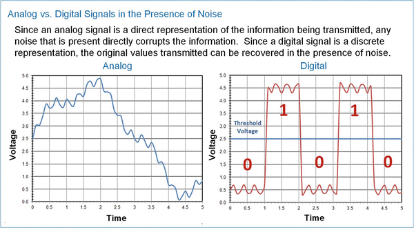
There are a variety of reasons that digital systems are preferred over analog systems. First is their ability to operate within the presence of noise. Since an analog signal is a direct representation of the physical quantity it is transmitting, any noise that is coupled onto the electrical signal is interpreted as noise on the original physical quantity. An example of this is when you are listening to an AM/FM radio and you hear distortion of the sound coming out of the speaker. The distortion you hear is not due to actual distortion of the music as it was played at the radio station, but rather electrical noise that was coupled onto the analog signal transmitted to your radio prior to being converted back into sound by the speakers. Since the signal in this case is analog, the speaker simply converts it in its entirety (noise+music) into sound. In the case of digital signaling, a significant amount of noise can be added to the signal while still preserving the original 1s and 0s that are being transmitted. For example, if the signal is representing a 0, the receiver will still interpret the signal as a 0 as long as the noise doesnt cause the level to exceed the threshold. Once the receiver interprets the signal as a 0, it stores the encoded value as a 0, thus ignoring any noise present during the original transmission. Figure . The analog signal is distorted; however, the digital signal is still able to transmit the 0s and 1s that represent the information.
Fig. 1.2
Noise on analog ( left ) and digital ( right ) signals
Another reason that digital systems are preferred over analog ones is the simplicity of the circuitry. In order to produce a 1 and 0, you simply need an electrical switch. If the switch connects the output to a voltage below the threshold, then it produces a 0. If the switch connects the output to a voltage above the threshold, then it produces a 1. It is relatively simple to create such a switching circuit using modern transistors. Analog circuitry, however, needs to perform the conversion of the physical quantity it is representing (e.g., pressure, sound) into an electrical signal all the while maintaining a direct correspondence between the input and output. Since analog circuits produce a direct, continuous representation of information, they require more complicated designs to achieve linearity in the presence of environmental variations (e.g., power supply, temperature, fabrication differences). Since digital circuits only produce a discrete representation of the information, they can be implemented with simple switches that are only altered when information is produced or retrieved. Figure shows an example comparison between an analog inverting amplifier and a digital inverter. The analog amplifier uses dozens of transistors (inside the triangle) and two resistors to perform the inversion of the input. The digital inverter uses two transistors that act as switches to perform the inversion.

