Manoj R. Thakur - NodeMCU ESP8266 Communication Methods and Protocols : Programming with Arduino IDE
Here you can read online Manoj R. Thakur - NodeMCU ESP8266 Communication Methods and Protocols : Programming with Arduino IDE full text of the book (entire story) in english for free. Download pdf and epub, get meaning, cover and reviews about this ebook. year: 2018, publisher: Amazon Media EU S.à r.l., genre: Computer. Description of the work, (preface) as well as reviews are available. Best literature library LitArk.com created for fans of good reading and offers a wide selection of genres:
Romance novel
Science fiction
Adventure
Detective
Science
History
Home and family
Prose
Art
Politics
Computer
Non-fiction
Religion
Business
Children
Humor
Choose a favorite category and find really read worthwhile books. Enjoy immersion in the world of imagination, feel the emotions of the characters or learn something new for yourself, make an fascinating discovery.
- Book:NodeMCU ESP8266 Communication Methods and Protocols : Programming with Arduino IDE
- Author:
- Publisher:Amazon Media EU S.à r.l.
- Genre:
- Year:2018
- Rating:3 / 5
- Favourites:Add to favourites
- Your mark:
NodeMCU ESP8266 Communication Methods and Protocols : Programming with Arduino IDE: summary, description and annotation
We offer to read an annotation, description, summary or preface (depends on what the author of the book "NodeMCU ESP8266 Communication Methods and Protocols : Programming with Arduino IDE" wrote himself). If you haven't found the necessary information about the book — write in the comments, we will try to find it.
Manoj R. Thakur: author's other books
Who wrote NodeMCU ESP8266 Communication Methods and Protocols : Programming with Arduino IDE? Find out the surname, the name of the author of the book and a list of all author's works by series.


NodeMCU ESP8266 Communication Methods and Protocols : Programming with Arduino IDE — read online for free the complete book (whole text) full work
Below is the text of the book, divided by pages. System saving the place of the last page read, allows you to conveniently read the book "NodeMCU ESP8266 Communication Methods and Protocols : Programming with Arduino IDE" online for free, without having to search again every time where you left off. Put a bookmark, and you can go to the page where you finished reading at any time.
Font size:
Interval:
Bookmark:
NodeMCU ESP8266 Communication Methods and Protocols Programming with Arduino IDE Manoj R. Thakur Table of Contents 1. Introduction
Volume production of the ESP8266 started in the beginning of 2014 ESP8266 IC is very tiny and virtually impossible for hobbyists to attach wires to allow them to be plugged into breadboards. For simplicity we can buy pre-made development boards such as NodeMCU board from e-bay, amazon for a few dollars on. There are a variety of board styles available. In this book we mainly focus on commonly used and easily available board NodeMCU . Recently Espressif released ESP32 more powerful low-cost microcontroller with dual core and large number of IOs and TLS 1.2, Capacitive touch pad, ADC, DAC, Bluetooth capability.
Here are some of the salient points:
- Operating Voltage: 3.3V
- Current consumption: 10uA 170mA
- Flash memory attachable 16MB max (512K normal)
- Processor Tensilica: L106 32-bit
- Processor speed: 80-160MHz
- RAM: 32K + 80K
- GPIOs: 17 (multiplexed with other functions)
- Analog to Digital 1 input with 1024 step (10 bit) resolution
- Wi-Fi: 802.11 support b/g/n
- Maximum concurrent TCP connections 5
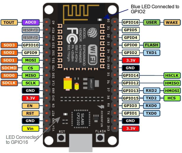 Figure 1.1: NodeMCU Pin Diagram
 Follow these steps Step 1: Open Arduino IDE Go to File >> Preferences Add additional board manager URLs: http://arduino.esp8266.com/stable/package_esp8266com_index.json 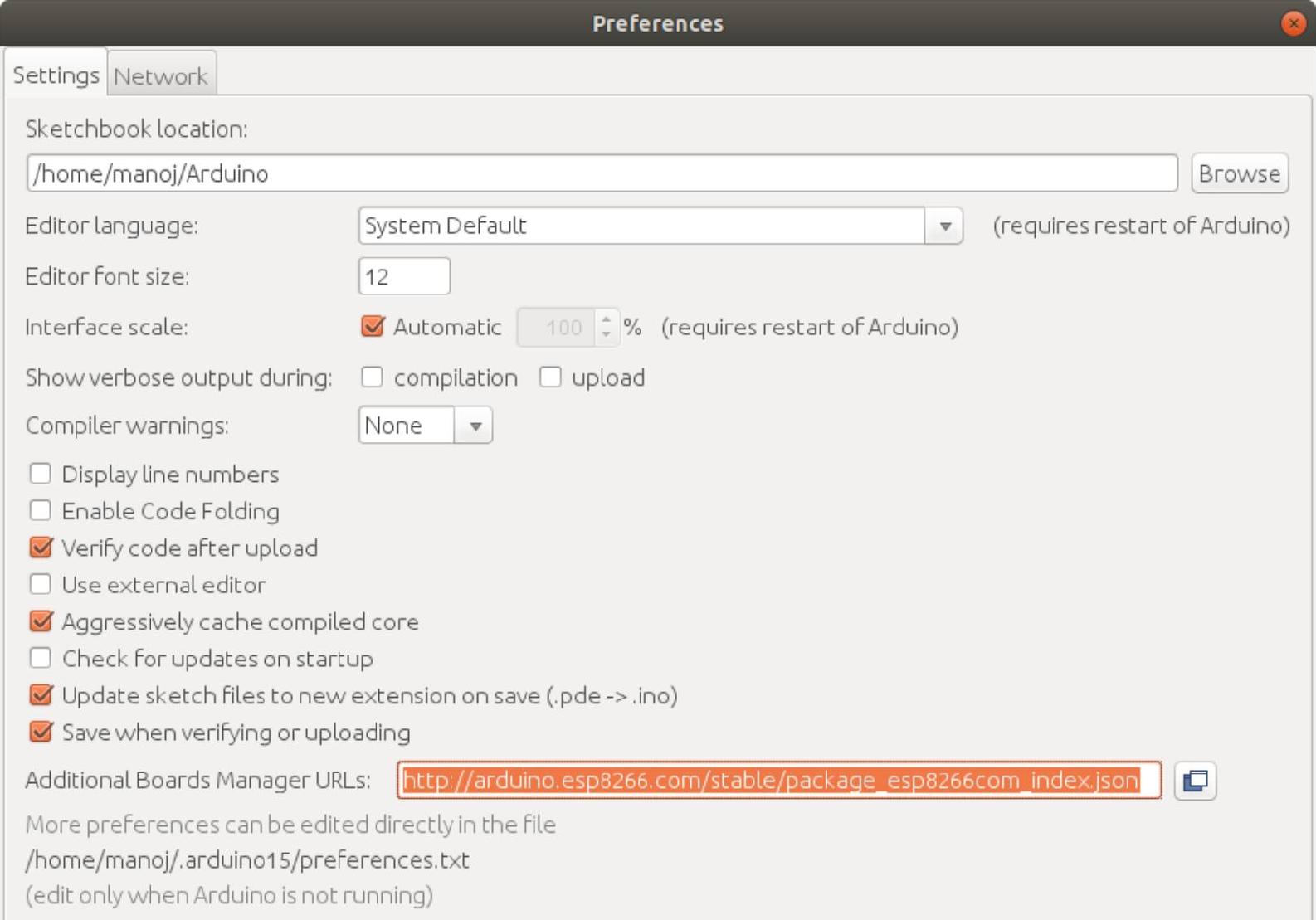 Figure 1.2: Preferences Step 2: Open Board Manager Go to Tools >> Board >> Board Manager
 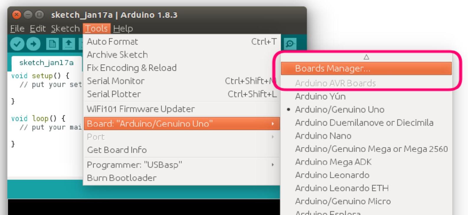 Figure 1.3: Board Manager Step 3: Install ESP8266 Board Search for ESP8266 and then click install button. Note: If Step 1 URL is not added then it will not find ESP8266 board.
 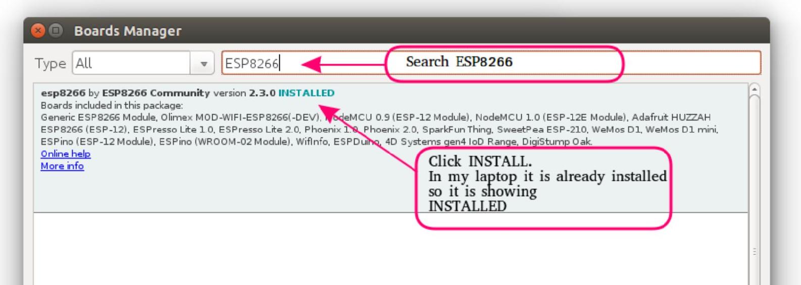 Figure 1.4: Install ESP8266 Step 4: After clicking install. Installation progress is shown in bottom. Once it is installed open Tools>>Boards and look for ESP8266.
Test LED blink program. Step 1: Select ESP8266 Generic Board or NodeMCU 1.0 Generic ESP8266 Module, Works for all boards so I prefer this board. 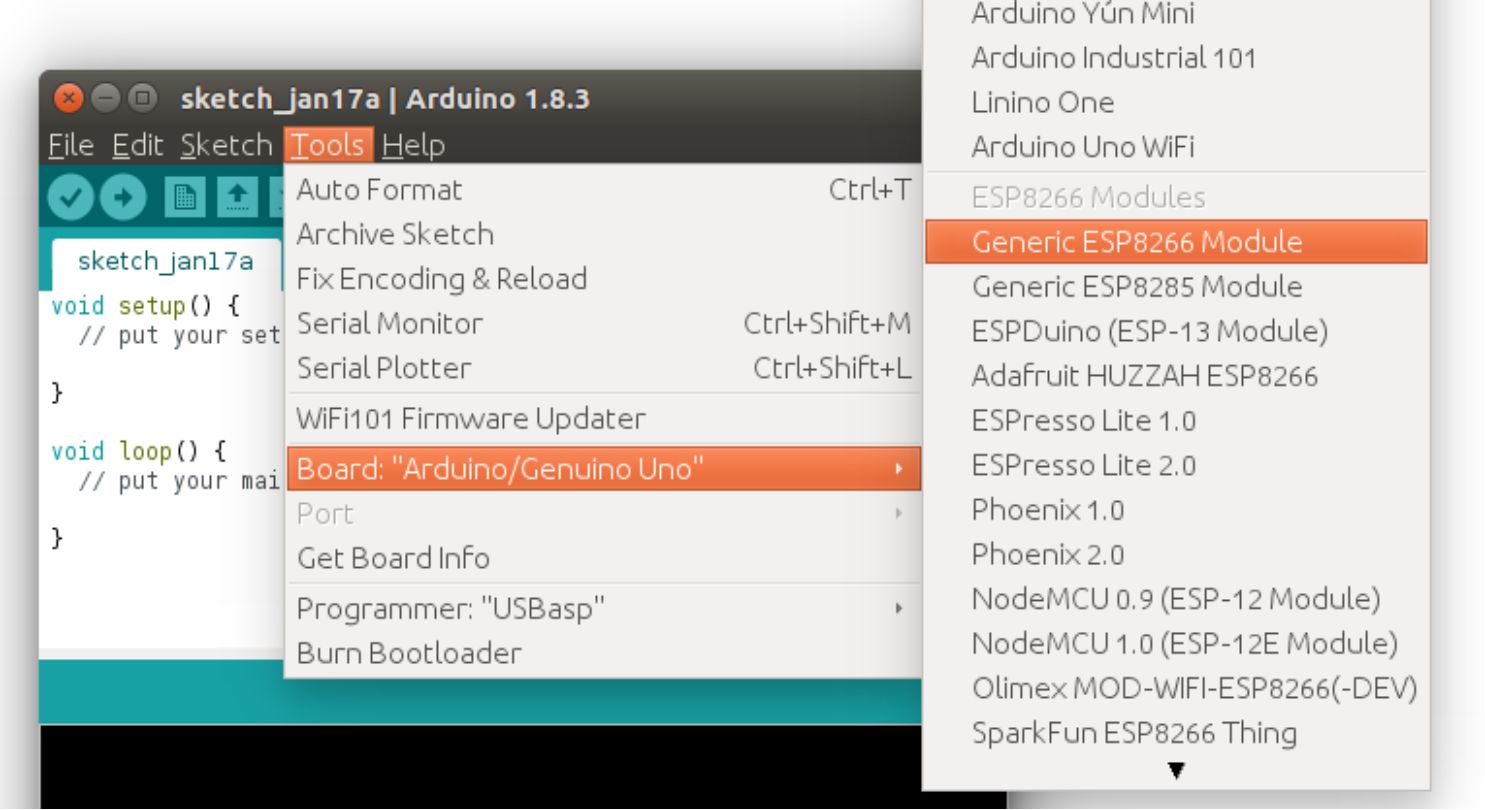 Figure 1.5: Board Selection Step 2: Open LED Blink Example of ESP8266
 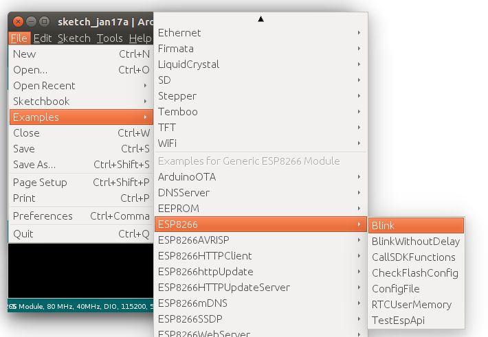 Figure 1.6: Open Blink Example Step 3: Modify or Write New Program to make GPIO2 LED blinking. NodeMCU is having two on board LEDs as shown in Figure 1.1. We use LED connected to GPIO2 for this example #define LED 2 void setup () { pinMode ( LED , OUTPUT ) ; //Define pin as output } void loop () { //LED off. LED is connected in reverse digitalWrite ( LED , HIGH ) ; delay ( ) ; digitalWrite ( LED , LOW ) ; //LED on delay ( ) ; } Step 4: Uploading Program to NodeMCU Select your boards com port.
Make sure that you have installed drivers for your board. NodeMCU uses CP2102 as USB to Serial converter. Install drivers for CP2102 if not installed. 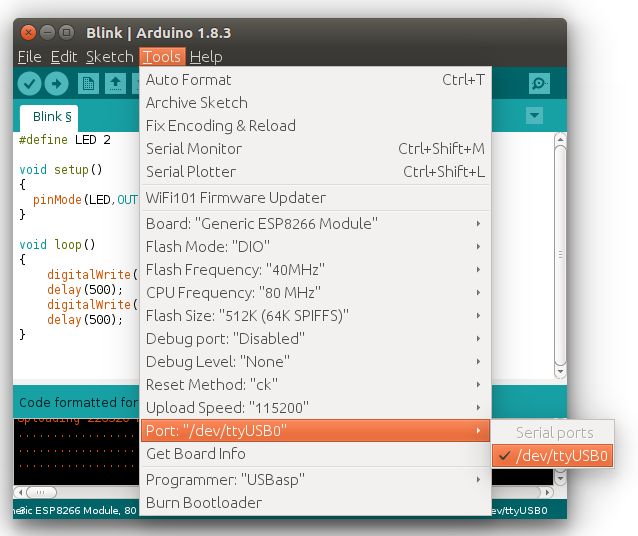 Figure 1.7: Communication Port Selection When you click on upload button press and hold FLASH button of NodeMCU which is present near USB connection, Once upload is started ( blue led blinks at faster rate ) you can release it. Pressing of FLASH button is not required if selected board is NodeMCU 1.0. Step 5: Once uploading is successful, check LED is blinking.
Now your setup is ready to go for further. 2. Serial Communication The first and basic most communication that is required for most of the devices and program debugging is serial communication. Its simple but important to know. Serial communication is used to make ESP communicate with PC and serial communication devices. ESP8266 RX TX line uses 3.3V logic.
All IO lines and supply voltage for ESP8266 is 3.3V. Do not connect any IO line with 5V logic
Example 1: Serial Data Transmission Program to send Hello World message to serial void setup () { Serial . begin ( 115200 ) ; } void loop () { Serial . println ( " Hello World " ) ; delay ( ) ; } Upload above program and open serial monitor to see transmitted data. 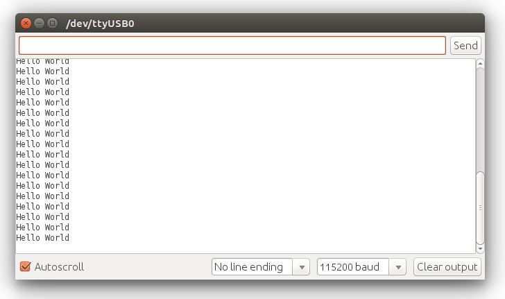 Figure 2.1: Serial output Serial may be remapped to GPIO15 (TX) and GPIO13 (RX) by calling Serial.swap() after Serial.begin . Calling swap again maps UART0 back to GPIO1 and GPIO3. Example 2: Remapping Serial to use GPIO15 (TX) and GPIO13 (RX) Remapping serial can be used to make interface of two serial devices.
But only one serial device is get connected to ESP8266 at a time. This is useful for interfacing RF ID reader, GPS, GSM device. void setup () { Serial . begin ( 115200 ) ; Serial . swap () ; //Remap RX TX to GPIO13(Rx) and GPIO15(Tx) } void loop () { Serial . println ( " Hello World " ) ; delay ( ) ; } Serial1 uses UART1, TX pin is GPIO2.
UART1 cannot be used to receive data because normally its RX pin is occupied for flash chip connection. To use Serial1, call Serial1.begin(baudrate) . Example 3: Using Serial-1 (Only TX) After uploading program you will see blue led flashes due to data is getting sent on GPIO2(TX). void setup () { Serial1 . begin ( 115200 ) ; } void loop () { Serial1 . void setup () { Serial . begin ( 115200 ) ; Serial . set_tx ( ) ; //Remap TX pin to GPIO2 } void loop () { Serial . println ( " Hello World " ) ; delay ( ) ; } After uploading program you will see blue led flashes due to data is getting sent on GPIO2(TX). println ( " Hello World " ) ; delay ( ) ; } After uploading program you will see blue led flashes due to data is getting sent on GPIO2(TX).
Font size:
Interval:
Bookmark:
Similar books «NodeMCU ESP8266 Communication Methods and Protocols : Programming with Arduino IDE»
Look at similar books to NodeMCU ESP8266 Communication Methods and Protocols : Programming with Arduino IDE. We have selected literature similar in name and meaning in the hope of providing readers with more options to find new, interesting, not yet read works.
Discussion, reviews of the book NodeMCU ESP8266 Communication Methods and Protocols : Programming with Arduino IDE and just readers' own opinions. Leave your comments, write what you think about the work, its meaning or the main characters. Specify what exactly you liked and what you didn't like, and why you think so.