Part I
Arduino Engineering Basics
In This Part
- Chapter 1: Getting Up and Blinking with the Arduino
- Chapter 2: Digital Inputs, Outputs, and Pulse-Width Modulation
- Chapter 3: Reading Analog Sensors
Chapter 1
Getting Up and Blinking with the Arduino
Parts Youll Need for This Chapter:
CODE AND DIGITAL CONTENT FOR THIS CHAPTER
Code downloads, videos, and other digital content for this chapter can be found at www.exploringarduino.com/content/ch1 .In addition, all code can be found at www.wiley.com/go/exploringarduino on the Download Code tab. The code is in the chapter 01 download and individually named according to the names throughout the chapter.
Now that you have some perspective on the Arduino platform and its capabilities, its time to explore your options in the world of Arduino. In this chapter, you examine the available hardware, learn about the programming environment and language, and get your first program up and running. Once you have a grip on the functionality that the Arduino can provide, youll write your first program and get the Arduino to blink!
NOTE To follow along with a video that introduces the Arduino platform, visit www.jeremyblum.com/2011/01/02/arduino-tutorial-series-it-begins/ . You can also find this video on the Wiley website shown at the beginning of this chapter.
Exploring the Arduino Ecosystem
In your adventures with the Arduino, youll depend on three main components for your projects:
- The Arduino board itself
- External hardware (including both shields and hand-made circuits, which youll explore throughout this book)
- The Arduino integrated development environment, or Arduino IDE
All these system components work in tandem to enable you do just about anything with your Arduino.
You have a lot of options when it comes to Arduino development boards, but this book focuses on using official Arduino boards. Because the boards are all designed to be programmable via the same IDE, you can generally use any of the modern Arduino boards to complete the projects in this book with zero or minor changes. However, when necessary, youll see caveats about using different boards for various projects. The majority of the projects use the Arduino Uno.
You start by exploring the basic functionality baked in to every Arduino board. Then you examine the differences between each modern board so that you can make an informed decision when choosing a board to use for your next project.
Arduino Functionality
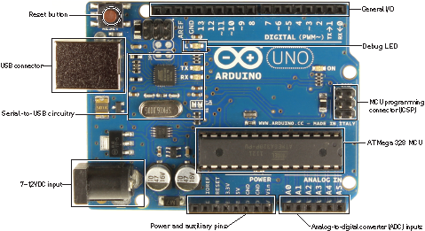
All Arduino boards have a few key capabilities and functions. Take a moment to examine the Arduino Uno (see ); it will be your base configuration. These are some key components that youll be concerning yourself with:
- Atmel microcontroller
- USB programming/communication interface(s)
- Voltage regulator and power connections
- Breakout I/O pins
- Debug, Power, and RX/TX LEDs
- Reset button
- In-circuit serial programmer (ICSP) connector(s)
: Arduino Uno components
Credit: Arduino, www.arduino.cc
Atmel Microcontroller
At the heart of every Arduino is an Atmel microcontroller unit (MCU). Most Arduino boards, including the Arduino Uno, use an AVR ATMega microcontroller. The Arduino Uno in uses an ATMega 328p. The Due is an exception; it uses an ARM Cortex microcontroller. This microcontroller is responsible for holding all of your compiled code and executing the commands you specify. The Arduino programming language gives you access to microcontroller peripherals, including analog-to-digital converters (ADCs), general-purpose input/output (I/O) pins, communication buses (including I2C and SPI), and serial interfaces. All of this useful functionality is broken out from the tiny pins on the microcontroller to accessible female headers on the Arduino that you can plug wires or shields into. A 16 MHz ceramic resonator is wired to the ATMegas clock pins, which serves as the reference by which all program commands execute. You can use the Reset button to restart the execution of your program. Most Arduino boards come with a debug LED already connected to pin 13, which enables you to run your first program (blinking an LED) without connecting any additional circuitry.
Programming Interfaces
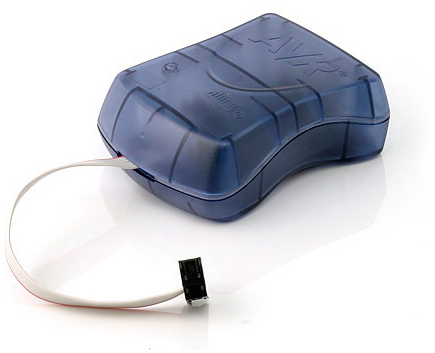
Ordinarily, ATMega microcontroller programs are written in C or Assembly and programmed via the ICSP interface using a dedicated programmer (see ). Perhaps the most important characteristic of an Arduino is that you can program it easily via USB, without using a separate programmer. This functionality is made possible by the Arduino bootloader. The bootloader is loaded onto the ATMega at the factory (using the ICSP header), which allows a serial USART (Universal Synchronous/Asynchronous Receiver/Transmitter) to load your program on the Arduino without using a separate programmer. (You can learn more about how the bootloader functions in The Arduino Bootloader and Firmware Setup sidebar.)
In the case of the Arduino Uno and Mega 2560, a secondary microcontroller (an ATMega 16U2 or 8U2 depending on your revision) serves as an interface between a USB cable and the serial USART pins on the main microcontroller. The Arduino Leonardo, which uses an ATMega 32U4 as the main microcontroller, has USB baked right in, so a secondary microcontroller is not needed. In older Arduino boards, an FTDI brand USB-to-serial chip was used as the interface between the ATMegas serial USART port and a USB connection.
: AVR ISP MKII programmer
Credit: 2013 Atmel Corporation. All rights reserved.
General I/O and ADCs
The part of the Arduino that youll care the most about during your projects is the general-purpose I/O and ADC pins. All of these pins can be individually addressed via the programs youll write. All of them can serve as digital inputs and outputs. The ADC pins can also act as analog inputs that can measure voltages between 0 and 5V (usually from resistive sensors). Many of these pins are also multiplexed to serve additional functions, which you will explore during your projects. These special functions include various communication interfaces, serial interfaces, pulse-width-modulated outputs, and external interrupts.
Power Supplies
For the majority of your projects, you will simply use the 5V power that is provided over your USB cable. However, when youre ready to untether your project from a computer, you have other power options. The Arduino can accept between 6V and 20V (7-12V recommend) via the direct current (DC) barrel jack connector, or into the Vin pin. The Arduino has built-in 5V and 3.3V regulators:
- 5V is used for all the logic on the board. In other words, when you toggle a digital I/O pin, you are toggling it between 5V and 0V.
- 3.3V is broken out to a pin to accommodate 3.3V shields and external circuitry.
The Arduino Bootloader and Firmware Setup
A bootloader is a chunk of code that lives in a reserved space in the program memory of the Arduinos main MCU. In general, AVR microcontrollers are programmed with an ICSP, which talks to the microcontroller via a serial peripheral interface (SPI). Programming via this method is fairly straightforward, but necessitates the user having a hardware programmer such as an STK500 or an AVR ISP MKII programmer (see ).

