Arduino Design Ideas and Practical Examples By Yury Magda Copyright 2020 by Yury Magda. All rights reserved. The programs, examples, and applications presented in this book have been included for their instructional value. The author offers no warranty implied or express, including but not limited to implied warranties of fitness or merchantability for any particular purpose and do not accept any liability for any loss or damage arising from the use of any information in this book, or any error or omission in such information, or any incorrect use of these programs, procedures, and applications. No part of this publication may be reproduced, stored in a retrieval system, or transmitted in any form or by any means, electronic, mechanical, photocopying, recording, or otherwise, without the prior written permission of the author.
About the Author Yury Magda is an engineer experienced in designing hardware and software for embedded systems.
He is also the author of the books on designing embedded systems based upon using Arduino, Raspberry Pi and FPGA.
Contents
Introduction
This book illustrates how to design Arduino-based applications using simple circuits and minimum coding. Many examples from this book were developed using a minimalist approach when only a few commonly used electronic components are required to build even complex systems. The source code of most of the examples is simple so even beginners can understand it. All designs described in this book are developed using Arduino Uno and Arduino Zero boards, although the source code can easily be adapted for other Arduino-compatible boards.
Disclaimer
While the author has used good faith efforts to ensure that the information and instructions contained in this book are accurate, the author disclaims all responsibility for errors or omissions, including without limitation responsibility for damages resulting from the use of or reliance on this work.
Use of the information and instructions contained in this work is at your own risk. If any code samples or other technology this book contains or describes is subject to open source licenses or the intellectual property rights of others, it is your responsibility to ensure that your use thereof complies with such licenses and/or rights. All example applications from this book were developed and tested using the Arduino Uno and Arduino Zero development boards without damaging hardware. As a software tool, the author used Arduino IDE 1.8.12. The author will not accept any responsibility for damages of any kind due to actions taken by you after reading this book.
Hardware
To develop the examples, two popular development boards, Arduino Uno and Arduino Zero, were used.
The Arduino Uno board ( Fig.1 ) is equipped with the Atmega328P microcontroller that is actively involved in the projects from this book. 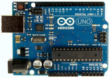 Fig.1 Below is the pinout diagram ( Fig.2 ) of Arduino Uno that we will use in circuit diagrams that accompany our projects.
 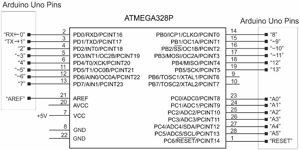 Fig.2 To simplify programming, we will use the necessary minimum of material presented in the Atmega328P datasheet. One more board being used is Arduino Zero ( Fig.3 ).
 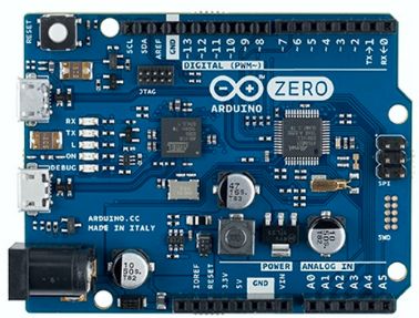 Fig.3 The Arduino Zero is a powerful board with the on-board 32-bit Microchip Atmel SAMD21 MCU (ARM Cortex M0+ core).
User Interfaces
Many examples in this guide requires some type of input-output user interface.
User Interfaces
Many examples in this guide requires some type of input-output user interface.
To display data provided by the applications, we will use a common LCD 16x2 display ( Fig.4 ). 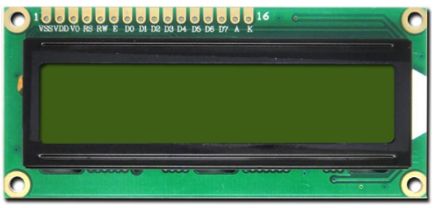 Fig.4 To control the LCD, we will apply the standard LiquidCrystal library. A brief description of this library taken from www.arduino.cc is given below. The library allows an Arduino board to control LiquidCrystal displays (LCDs) based on the Hitachi HD44780 (or a compatible) chipset, which is found on most text-based LCDs. The library works with in either 4- or 8-bit mode (i.e. using 4 or 8 data lines in addition to the rs , enable , and, optionally, the rw control lines).
In this guide, we will use the following syntax LiquidCrystal(rs, enable, d4, d5, d6, d7), where rs is the number of the Arduino pin connected to the RS pin on the LCD, enable the number of the Arduino pin connected to the enable pin on the LCD. Our LCD will operate in the 4-bit mode where d4, d5, d6 and d7 are the numbers of the Arduino pins that are connected to the corresponding data pins on the LCD. Below is the simplest example of using the LCD ( Listing 1 ). Listing 1 . #include // initialize the library with the numbers of the interface pins LiquidCrystal lcd(4, 5, 8, 9, 10, 11); void setup() { // set up the LCD's number of columns and rows: lcd.begin(16, 2); // set the cursor to column 0, line 0 lcd.setCursor(0, 0); // Print a message to the LCD lcd.print("Seconds passed:"); } void loop() { // set the cursor to column 0, line 1 lcd.setCursor(0, 1); // print the number of seconds since power is on: lcd.print(millis()/1000); } In this example, the connections of the interface pins are as follows: pin of Arduino Uno is connected to the rs line of the LCD, pin is connected to the enable line, pins , , and of Uno are connected to the data lines d4 , d5 , d6 and d7 , respectively. 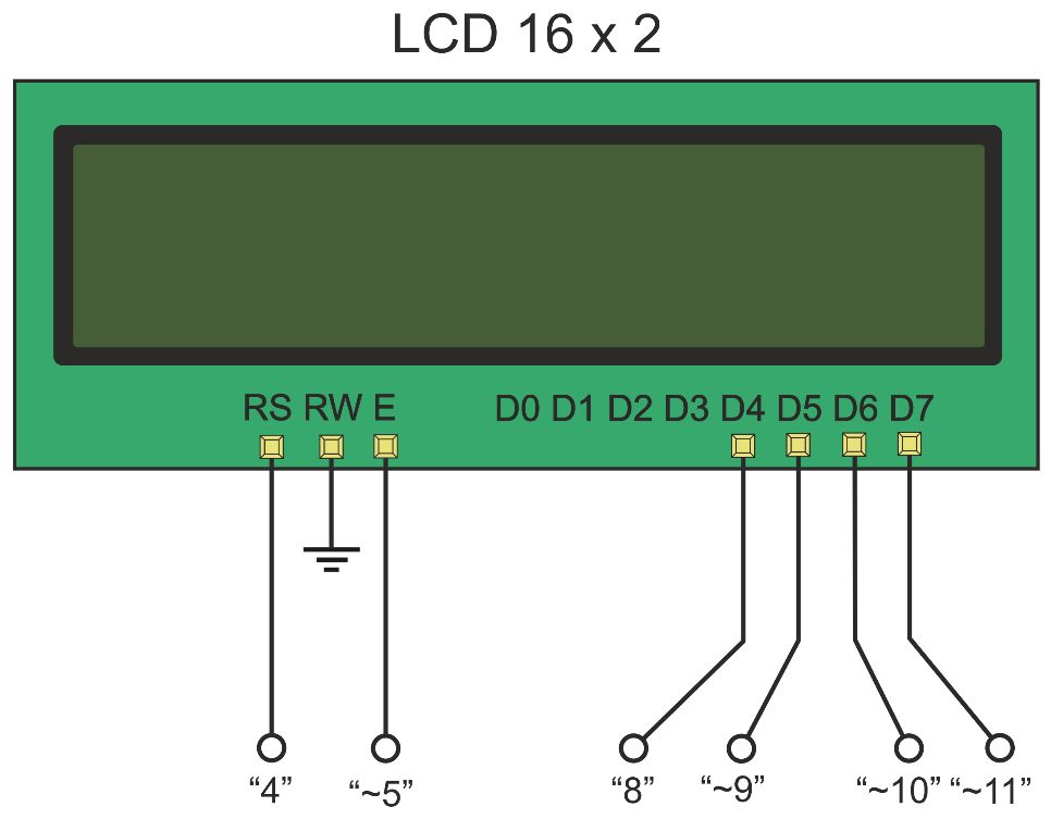 Fig.5 It is convenient to use free pins of Arduino Uno to interface the LCD.
  Fig.5 It is convenient to use free pins of Arduino Uno to interface the LCD.
For example, the unused analog pins A2-A5 can be assigned to the LCD data lines by the following statement LiquidCrystal lcd(4, 5, A2, A3, A4, A5); One more simple user-friendly interface being used in the examples from this book is the 16x2 LCD Keypad Shield for Arduino from SaintSmart. This board looks like the following ( Fig.6 ). 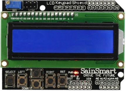 Fig.6 Note that there exist many clones of the LCD KeyPad Shield providing the same interface so you can use any of them. This shield includes a 1602 white character blue backlight LCD and a keypad consisting of 5 keys: SELECT , UP , DOWN , LEFT and RIGHT . To save the Arduino digital I/O pins, the keypad interface uses a single ADC channel A0 .
  Fig.7 The binary code on the analog input A0 depend on the key being pressed.
  Fig.7 The binary code on the analog input A0 depend on the key being pressed.
By default, the A/D converter operates at 10-bit resolution and the reference voltage (Vref) = 5.0V, therefore the code values for various keys will be close to those shown in the table below.
Next page





 Fig.1 Below is the pinout diagram ( Fig.2 ) of Arduino Uno that we will use in circuit diagrams that accompany our projects.
  Fig.2 To simplify programming, we will use the necessary minimum of material presented in the Atmega328P datasheet. One more board being used is Arduino Zero ( Fig.3 ).
  Fig.3 The Arduino Zero is a powerful board with the on-board 32-bit Microchip Atmel SAMD21 MCU (ARM Cortex M0+ core).
 Fig.4 To control the LCD, we will apply the standard LiquidCrystal library. A brief description of this library taken from www.arduino.cc is given below. The library allows an Arduino board to control LiquidCrystal displays (LCDs) based on the Hitachi HD44780 (or a compatible) chipset, which is found on most text-based LCDs. The library works with in either 4- or 8-bit mode (i.e. using 4 or 8 data lines in addition to the rs , enable , and, optionally, the rw control lines).
 Fig.5 It is convenient to use free pins of Arduino Uno to interface the LCD.
  Fig.6 Note that there exist many clones of the LCD KeyPad Shield providing the same interface so you can use any of them. This shield includes a 1602 white character blue backlight LCD and a keypad consisting of 5 keys: SELECT , UP , DOWN , LEFT and RIGHT . To save the Arduino digital I/O pins, the keypad interface uses a single ADC channel A0 .
  Fig.7 The binary code on the analog input A0 depend on the key being pressed.