1. Getting Started with Electronic Circuits
Most of this book involves connecting circuits to a Raspberry Pi, but before you actually plug anything into the Raspberry Pi, you will need a basic understanding of electronic circuits. This is going to be a gentle introduction, so if you already know how to build your own simple circuits and would like to jump straight in to connecting into the Raspberry Pi, feel free to jump to Chapter .
An electronic circuit combines individual electronic components to perform a specific function. This could be as simple as a light circuit in a torch/flashlight that turns on when the on switch is pressed or incredibly complex such as the circuitry inside a laptop computer. Electronic circuits are all built around the same principles.
The most basic principle is the concept that an electronic circuit must make a complete physical circuit. So for a circuit that includes a battery, there must be a complete path starting from the positive (+) side of the battery, through any components (such as a switch and buzzer), and then back to the negative (-) side of the battery. This is shown in the circuit in Figure .
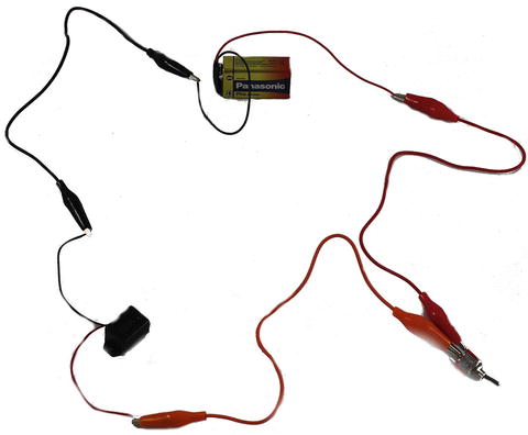
Figure 1-1.
Switch and buzzer circuit
This is a simple circuit connected using crocodile clip leads. The circuit has a buzzer and a switch, which can turn the buzzer on and off. When the switch is closed (turned on), the circuit is complete, allowing current to flow around the circuit, and the buzzer will sound. When the switch is open (off), there is a gap between the connections inside the switch preventing the current flow and causing the buzzer to stop.
Obviously this is a very basic circuit, but its also the basis of almost all the circuits youll make. You will replace the mechanical switch with an electronic component and use different sensors to turn the switch on and off. You will also use different outputs, including LEDs and motors.
Voltage, Current, and Resistance
Im going to keep the theory as simple as possible, but voltage, current, and resistance are some terms that I use throughout the book. Understanding how the circuit works and the math involved is going to be important by the time you get to the stage where you are designing your own circuits. I have avoided putting too much math into the projects, but there are some worked examples that you may find useful in future.
The voltage is the difference in energy between two terminals or points in a circuit. It is measured in volts indicated by a letter V. For example, you could have a 9V PP3 battery such as the one used in the buzzer circuit in Figure . The battery has a difference of 9 volts between its positive and negative terminals. We would consider the negative terminal to be at 0 volts and the positive terminal at 9 volts. The 0V connection is considered the ground terminal with voltages relative to that point. Although the battery is designed for 9V, the actual voltage may vary depending on how much charge is in the battery and what load is connected to it.
The current is the flow of electric charge around a circuit. Current is measured in amperes . This is normally abbreviated to amps and its value is indicated by a letter A. The current is related to the voltage: the higher the voltage of the power supply, the more current is able to flow through the circuit, although it also depends on what other components are in the circuit. Using conventional electric current, you say that the current flows from the positive to the negative terminal. In the electronic circuits youll create, most currents will be small and so will normally be measured in milliamps (mA), where 1mA = 0.001A.
The electrical resistance is a measure of how difficult it is for the current to flow around a circuit. It is measured in ohms . The value ohms is represented by the Greek omega character (). There is resistance in all components of a circuit, but you can normally disregard the small amount of resistance in a good conductor such as a wire. The resistors you will be using normally range from around two hundred ohms to several thousand ohms (k).
Ohms Law
When creating advanced circuits, some of the math can get quite complicated; fortunately, you dont need to do many calculations for most of the circuits in this book. However, there are still some basic calculations that you will need to do to. In particular for some of the circuits, you will need to work out a suitable resistor size to ensure that the current cannot damage any components, but is sufficient to allow the circuit to work.
To do this, you use a single formula thats almost certainly the most important formula used in electronics. Its also one of the simplest. This relationship was discovered by German scientist Georg Ohm and is known as Ohms Law. The basic formula is this:
I = V/R
As you may expect, V represents voltage and R represents resistance (measured in ohms), but I is not so obvious. I is used to indicate current, based on the French phrase, intensit de courant.
So this formula says that to find the current through a circuit, divide the voltage by the resistance. This can be rearranged to find the voltage using this formula:
V = I x R
To calculate the required resistor size, use:
R = V/I
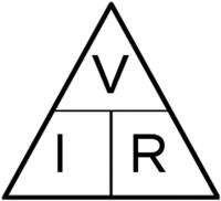
An easy way to remember this is using the Ohms Law triangle, shown in Figure .
Figure 1-2.
Ohms Law triangle
To use the triangle, hide the value you want to calculate and read the remaining entries. So to find the voltage, you hide the letter V, leaving I and R. So multiply the current and resistance to find the voltage. To find the required resistor size, hide the letter R which leaves V above I. So you divide the voltage by the current to get the required resistor size.
Electrical Safety
Electricity can be dangerous. All the projects in this book are designed to work at low voltages up to 12V and, as long as an appropriate safe power supply (such as a wall wart or plug-in power supply) is used, there is little risk of electric shock. The same does not apply to the high voltage present in the main electricity supply.
In fact its not the voltage thats dangerous but the amount of current that can flow through the body. Electric fences used for farm animals give a shock of several thousand volts, but although they give a nasty shock, they are considered safe for use near people as they are limited to short bursts of very low current (although should still be avoided particularly by children or those with heart conditions). The main electricity to your house is between about 100V and 250V (depending on which country you live in) and is very dangerousit can supply enough current to be fatal. As a general rule to avoid any risk of electric shock, I recommend only working with circuits designed for 24V or less, unless you are 100% sure you know what you are doing.
Its not only electric shock that poses a risk. Even at much lower voltages, too much current can create a lot of heat and potentially start a fire. This is particularly important when using low voltage (12V) electrical lighting or car batteries, which can provide very high currents in the event of a short-circuit. I recommend only using power supplies with short-circuit and over-current protection and consider adding a fuse (this is explained later during the disco lights project).