Best Arduino Automation Project
Index Of Contents
Wouldnt it's exquisite to water your greenhouse with out leaving your chair, or open your garage door remotely?
Rather than permit your Arduino sit down on a shelf amassing dust (were all responsible of that occasionally), have interaction it as the key issue of some home automation projects. Weve compiled this list of 5 to show you simply what is feasible.
One of the super matters about Arduino home automation projects is that with the addition of an Ethernet protect, you can flip your Arduino into a web-connected tool, able to transfer lighting, TVs, coffee machines pretty a lot something you may think of on and off, the use of both a browser-primarily based interface or a timer. See my littleBits infra-crimson mild transfer challenge for a evidence of idea the identical can be completed with an Arduino.
1. Arduino Powered Service Elevator
Layout and take a look at a manipulate device for a provider raise working for four floors. The microcontroller (ATMega2560) is used to decide which contactor to provide strength for you to set off the carry motor to transport the raise up or down by means of checking the floor the lift is currently at. The control gadget ought to be additionally capable of prevent the energy to the lift whilst it has reached the desired floor. An integral safety factor must be implemented to continually close the lift door earlier than transferring up or down. The manage device is successfully able to determine which contactor wishes to be powered which will circulate the elevate to the desired ground. The gadget is able to manipulate the protection carry door motor for you to near the door whilst the elevate wishes to transport and open the door automatically while it has reached the specified ground.
1. Three Phase Motor Wiring
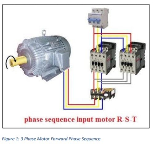
A three section motor is used in this software as this is requires a powerful motor which could cope with a heavy load. The 3 section motor is powered via the primary 3 phase strength. power through the mains runs thru two fundamental contactors. while the primary contactor is switched on and the second contactor is switched off, power runs via the primary contactor to the winding of the motor which moves the motor inside the forward direction.
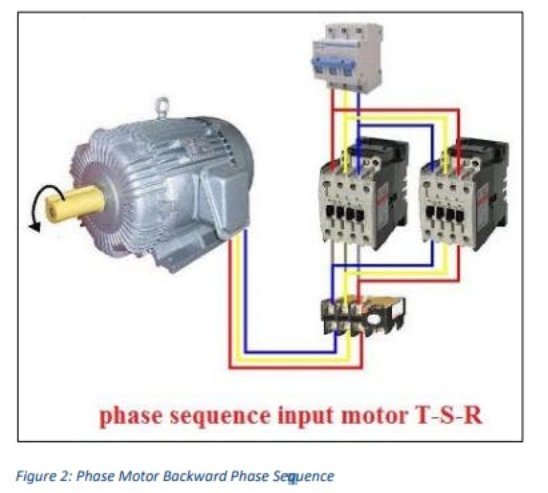
when the second one contactor is switched on and the primary contactor is switched off, power runs thru the second contactor to the winding of the motor which actions the motor within the backward direction. word that the wiring is different for the reverse course.
2. Ground Detection
so one can stumble on the floor the raise is presently at, a restrict switch is used. because the elevate movements up or down it closes and opens a restriction turn on each floor. when the lift is at a specific ground the limit floor at that particular floor is closed indicating to the microcontroller the ground the elevate is at. because the carry actions the limit switch opens indicating to the microcontroller that the lift is transferring.
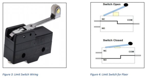
The transition from low to excessive signal produced with the aid of the limit transfer whilst the lift moves through a floor takes place in a fragment of a second and regularly too quick to be detected by way of the microcontroller. The restriction switches are related to a 5V DC supply and the output from the NO(commonly Open) terminal is hooked up to an IO pin of the microcontroller. 4 limit switches at four flooring ship facts to the microcontroller. This enables the microcontroller to determine the ground the elevate is at with the aid of checking which pin went from low to excessive. The transition of a restrict switchs nation is proven inside the diagram underneath:
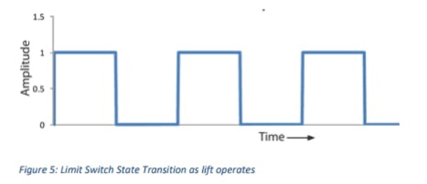
The problematic challenge is to permit the microcontroller to hit upon the transition from low to excessive. There are two methods to method this problem. First technique is to decide if a restrict transfer pin is going excessive in the loop characteristic using an if circumstance. the program basically whilst executing other code continually tests if a pin is going high. This takes up a variety of reminiscence as the application is continuously searching out a high sign from a limit transfer pin. every other problem is that occasionally the program might leave out this transition as the loop feature turned into executing a few other code while a transition takes place. if you want to avoid those troubles, Interrupts are used. Interrupts essentially pause the execution of code and execute a separate feature while a selected interrupt circumstance is satisfied. This is right for the carry operation. whilst a restriction transfer pin goes from low to excessive an interrupt characteristic is executed and this function tests if the lift is on the modern-day floor and stops the lift or allow it to move further. for the reason that application is forced to execute the interrupt feature whilst a restrict switch is switched the system can ensure that this system does now not intentionally skip detecting a ground.
The microcontroller used for this application is the Arduino Mega 2560 which has 6 digital pins usable for interrupts which is ideal to use for the 4 flooring. the first parameter to attachInterrupt is an interrupt quantity. usually you have to use digitalPinToInterrupt(pin) to translate the actual digital pin to the precise interrupt range. as an instance, in case you connect with pin 3, use digitalPinToInterrupt(3) because the first parameter to attachInterrupt. it's also critical to note that the put off() function receivedt work in the function accomplished by way of the Interrupt provider habitual(ISR).
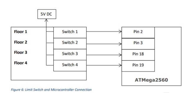
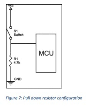
The diagram above shows how the restriction switches are related to the MCU. The pins in the MCU are related through a pull down resistor. This resistor pulls down the pin of the MCU to floor to ensure that a LOW voltage analyzing is examine through the MCU when the restriction switch is left open. The resistor configuration is proven within the diagram underneath.
3. Motor Up and Down control
two 12V DC relays are used to interchange AC electricity to the contactors of the motor which manipulate its path (either Up or Down). The circuit designed using Multisim is shown within the diagram underneath:
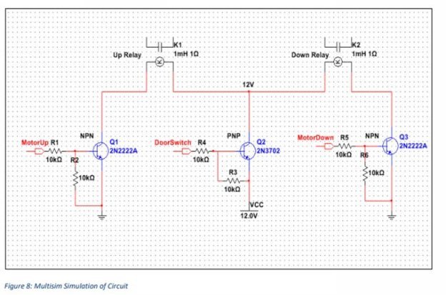
One cease of the coil contactor of each the relays are related to the 12V DC supply through a PNP transistor. the primary reason of doing that is to ensure that the Motor isn't always supplied energy until the raise door is closed. as soon as the lift door is closed, the DoorSwitch output pin to the gate of the PNP transistor is pulled to floor ensuring that the PNP is became directly to offer the VCC strength to both the relays. consequently the relay isn't became on even though the MotorUp or MotorDown signal is excessive. the alternative end of the relay coil is pulled to ground via a NPN transistor. The MotorUp signal is generated from the MCU. whilst the MotorUp sign is excessive, the primary NPN transistor is activated and it pulls the other coil contact to floor to complete the circuit to energy the coil of the Up Relay to electricity the motor. The identical method is used to set off the Down Relay. motives for the usage of transistors to replace the Relays are:


