Springer International Publishing AG 2017
Eugeniusz Rusiski and Damian Pietrusiak (eds.) Proceedings of the 13th International Scientific Conference Lecture Notes in Mechanical Engineering 10.1007/978-3-319-50938-9_1
Dynamic Analysis of Column Stand for Aircraft Multi-barrel Machine Gun with Consideration of Bearing Clearance
Pawe Abratowski 1
(1)
Institute of Aviation, Transport Systems Department, Aviation Structures and Design Department, Al. Krakowska 110/114, Warsaw, 02-256, Poland
(2)
Faculty of Mechanical Engineering, Department of Mechanics and Applied Computer Science, Military University of Technology, Kaliskiego Street 2, 00-908 Warsaw, Poland
Pawe Abratowski (Corresponding author)
Email:
Wodzimierz Gnarowski
Email:
Abstract
To build a machine gun on a helicopter board or on a vehicle, a sufficiently rigid and strong stand is required []. The construction of a column stand ensures changing a shot direction in the vertical plane and rotation in the horizontal plate. In a bearing of the column, a clearance can occur. It can cause a change in accuracy of a trajectory angle of the bullet. The paper presents a dynamic analysis of a machine gun taking into account clearance in the bearing. The target of the analysis is to find an impact of clearance on the trajectory angle of the bullet.
Introduction
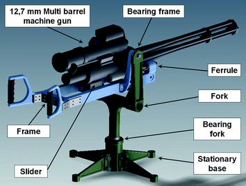
One of the topics developed at the Warsaw Institute of Aviation in cooperation with military mechanical plants is a design of a column stand for a multi-barrel machine gun. The column stand allows mounting the gun on a helicopter board or on a vehicle board [. The column consists of a stationary base, a fork and a frame. The fork is installed to the base and may be rotated around the vertical axis. The frame is pivotally installed with the fork. The gun is installed to the ferrules (front part of the frame) and the slider (central part).
Fig. 1
The column stand construction
In order to examine the stiffness of the column, it is necessary to carry out computational dynamic analysis verifying the structure response to dynamic force. The calculations are performed for a series of force impulses coming from a gun shot. Numerical analysis of the machine gun stand includes:
Two variants of the FE model are built:
Model 1a column without bearing clearance,
Model 2modification of Model 1 with bearing fork clearance.
In the stand structure the Rayleigh Damping model (1) is applied:
where, = 0.001, = 0 (at this stage of research),
Mmass matrix, Kstiffness matrix.
The Model of Load
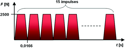
The column stand is loaded by a series of force impulses. An impulse of force is determined from the following data: the mass of the bullet, the initial velocity, the frequency of shots and maximal recoil force (2.5 kN, experimental data). There is no experimental data of the recoil force time-dependent, therefore at this stage of research, the force impulse (2) [.
where, Hgrowth momentum, Vvelocity, Fforce, ttime,
mmass of bullet.
Numerical Models
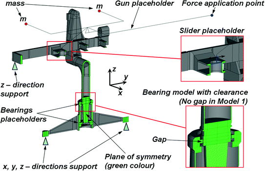
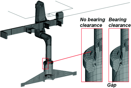
The considered model of the gun stand is symmetrical, therefore, the plane of symmetry is applied. For future simplification, a half of the gun stand is modeled in a form of the structure made of rigid beam elements and two concentrated masses. The masses are arranged in such a manner that the moment of inertia corresponds to the real one. The load is applied at the end of the barrel. As mentioned above, two computational models have been created:
Model 1a column without bearing clearance,
Model 2modification of Model 1 with changes allowing the bearing clearance simulation. At this stage of research 0.5 mm clearance is assumed. This is maximum allowable operation value. The upper bearing fork can fail as first, therefore it is taken to account. It was mapped in the model with taking into consideration the gap along the radius is applied.
The geometric model details are shown in Fig..
Fig. 4
Geometric model of a half of the gun stand
The FE models are developed using 8-nodal solid elements (3 degrees of freedom in each node), 8-nodal shell elements (6 degrees of freedom in each node). The gun placeholder is built of concentrated mass elements (a point element with 3 degrees of freedom) and 2-nodal link elements (3 degrees of freedom in each node). These elements are constrained as a rigid region. The gap is meshed using contact elements. The numerical FE model is shown in Fig..
Dynamic Analysis Using FEM
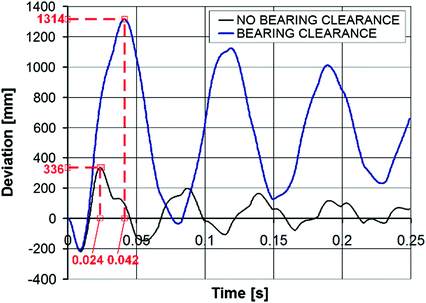
Transient dynamic analysis is performed using ANSYS solver [, respectively.
Fig. 6
Comparison of the deviations on the target for both cases
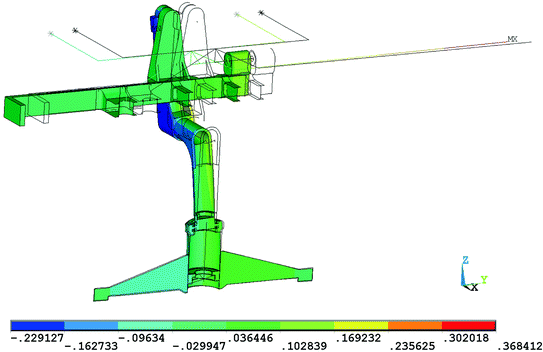
Fig. 7
Vertical displacements (z-direction)Model 1; no bearing clearance
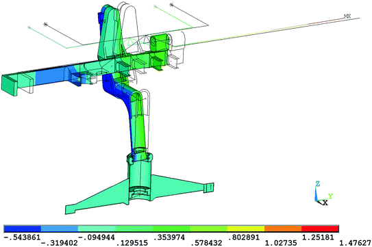
Fig. 8
Vertical displacements (z-direction)Model 2; bearing clearance applied
Conclusions
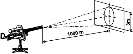
0.5 mm clearance of the bearing causes deviation increasing up to four times in comparison to the model without clearance. The deviation increases to the assumed limit of 3 m for a shot distance of 1000 m. Clearance greater than 0.5 mm may not meet the established limit criterion.


