Happyson Gavi - Troubleshooting Automotive Computer Systems: Automotive Computers, Sensors & Network
Here you can read online Happyson Gavi - Troubleshooting Automotive Computer Systems: Automotive Computers, Sensors & Network full text of the book (entire story) in english for free. Download pdf and epub, get meaning, cover and reviews about this ebook. year: 2015, publisher: Happyson Gavi, genre: Science. Description of the work, (preface) as well as reviews are available. Best literature library LitArk.com created for fans of good reading and offers a wide selection of genres:
Romance novel
Science fiction
Adventure
Detective
Science
History
Home and family
Prose
Art
Politics
Computer
Non-fiction
Religion
Business
Children
Humor
Choose a favorite category and find really read worthwhile books. Enjoy immersion in the world of imagination, feel the emotions of the characters or learn something new for yourself, make an fascinating discovery.
- Book:Troubleshooting Automotive Computer Systems: Automotive Computers, Sensors & Network
- Author:
- Publisher:Happyson Gavi
- Genre:
- Year:2015
- Rating:4 / 5
- Favourites:Add to favourites
- Your mark:
Troubleshooting Automotive Computer Systems: Automotive Computers, Sensors & Network: summary, description and annotation
We offer to read an annotation, description, summary or preface (depends on what the author of the book "Troubleshooting Automotive Computer Systems: Automotive Computers, Sensors & Network" wrote himself). If you haven't found the necessary information about the book — write in the comments, we will try to find it.
Happyson Gavi: author's other books
Who wrote Troubleshooting Automotive Computer Systems: Automotive Computers, Sensors & Network? Find out the surname, the name of the author of the book and a list of all author's works by series.

Troubleshooting Automotive Computer Systems: Automotive Computers, Sensors & Network — read online for free the complete book (whole text) full work
Below is the text of the book, divided by pages. System saving the place of the last page read, allows you to conveniently read the book "Troubleshooting Automotive Computer Systems: Automotive Computers, Sensors & Network" online for free, without having to search again every time where you left off. Put a bookmark, and you can go to the page where you finished reading at any time.
Font size:
Interval:
Bookmark:
TROUBLESHOOTING AUTOMOTIVE COMPUTER SYSTEMS
By
Happyson Gavi
CONTENTS
Chapter 1 . PCM in a Bus Network
Chapter 2 . CAN BUS System
Chapter 3 . Onboard diagnostics OBDI & OBDII
Chapter 4 . Automotive Computer Fundamentals
Chapter 5 . PCM to Sensor Communication & Storage Devices
Chapter 6 . PCM Architecture
Chapter 7 . Sensing Devices
Chapter 8 . I deal Air/Fuel Ratio
Chapter 9. Sensors used to calculate air/fuel ratio
Chapter 10 . Introduction to Emission Control
Chapter 11 . Automotive Emission Controls
Chapter 12 . Dealing with Common DTCs
Chapter 13 . Charging System
Chapter 1
1.1 PCM in a BUS Network
The abbreviation PCM stands for Power Control Module. PCM is the main automotive computer used to achieve various purposes mostly oriented toward transmission, engine management and performance. The PCM is one of the several on-board computers that are interconnected in an automotive vehicle forming a network system called CAN BUS, (CAN) for Controller Area Network, BUS is a form of network topology in which different in board computers / modules on different locations are connected to the main cable. BUS network topology is similar to passengers inside a bus sitting on seats that are located on different locations but sharing the same passage. CAN network provide an intercommunication system of various vehicle computers to make a CAN BUS system. The CAN BUS system shares data to each computer connected to the data link. Each computer in the data link is sometimes called a node. The PCM which is the main computer has the ultimate control of the Data BUS.
In brief the PCMs primary function is to manage Powertrain. This includes the ignition system, fuel system and emission system. PCMs ultimate goal is to ensure that the sensors work properly and that the car is non-polluting.
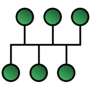
Fig1.1: A diagram illustrating a general BUS network topology.
1.2 What is BUS topology?
In such type of topology, a long backbone cable (twisted pair cable in CAN BUS) is used to link all the devices in the network. Wires are twisted to eliminate electrical noise. Twisted pair cable is used to link all the devices in the network. Drop lines and taps are used to connect different nodes/modules to this backbone. This topology allows only one device to transmit at a time since all nodes on the network share a common BUS. The node to transmit next is determined by distributed access protocol. This network topology helps to eliminate redundant wiring to the modules / EC U s that need the same sensor information.
1.2.1 Advantages of BUS topology
Requires less cabling and therefore less expensive as compared to mesh, star and tree topologies.
Easier to install than other topologies
Weight reduction due to fewer components
1.2.2 Disadvantages of BUS topology
I t s difficult to add new devices
I t s difficult to do reconfiguration
I t s difficult to isolate faults in nodes
Limited cable length required
Limited number of nodes that can be connected
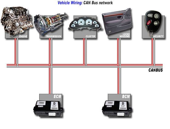
The number of accessories inside automobile increased rapidly in the last three decades. A typical late model vehicle will have 10 or more modules. This therefore implies that the number of actuators, sensors, navigation, entertainment, climate control etc. and their corresponding electronic control modules increased as well. Since modern electronics is almost completely digital this therefore implies for the need for efficient communication that is immune to interruption and noise using defined protocol. The communication between all on-board computers requires a network. This network allows all on-board computers to communicate with each other as well as scan tool communications. Engineers noted that BUS network topology was an effective mode of communication and came up with CAN BUS system
Chapter 2
2.1 CAN BUS system
A serial BUS that was developed in 1983 by Robert Bosch GmbH and was officially released in 1986 at the Society of Automobile Engineers (SAE) congress in Detroit Michigan for in-vehicle network in cars. CAN BUS employ twisted wires to eliminate radio frequency interference (RFI) and electromagnetic interference (EMI) from entering the system. The twisted wire is terminated at each end with 120 Ohm resistor called a Termination Resistor. The total resistance of the two terminating resistors connected in a twisted pair BUS sums up to 60 Ohms since the 2-resistors are connected in parallel. If one end of a twisted pair wire is open a 120 Ohm will be measured across pin 6 and 14 of the data link connector (DLC) with the ignition switch turned off and negative battery terminal being disconnected. If both wires are open an OL will be indicated on a DMM. Such CAN BUS is not reliable for data transmission and in many cases it might fail to operate.
CAN is the fastest network and its twisted wire can transmit at speeds up to one million bits per second.
CAN network allow different modules to share common sensor data like vehicle speed, outside air temperature, coolant temperature and density of air. Such information is essential for fuel trim and transmission shifting. Examples of modules that were programmed to use same vehicle speed signal are powertrain control module (PCM), cruise control module (CCM), anti-lock brake control module (ABS)and drive r s door module (DDM)
CAN system was also designed to function in the harsh automotive / truck environment. The CAN BUS is one of the 5-protocols used in the on-board diagnostics or OBD2 diagnostic standard. The OBD2 has been maintained for all cars and light truck sold in the USA since 1986.
2.1.1 Why 120 Ohms terminating resistor?
The 120 came up as a result of considering the Transmission Line Theory of Physics
This theory takes into consideration the length of BUS wires
The length is determined in terms of wavelengths
The terminating resistors prevent signal reflections causing interference
All devices in the network have to conform to the BUS impedance
When CAN BUS is at 60 (meaning two 120 in parallel as shown in Fig 2.1.1) the BUS can absorb all energy for maximum efficiency of the system
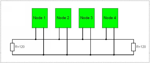
Fig 2.1.1: illustration of a CAN BUS network with 120 ohm terminating resistors
2.2 CAN Communications Protocols
Protocols are a system of digital rules or procedures for data exchange within or between computers. More precisely Protocols have more to do with the way data is formatted, transmitted and received.
ISO9131-2
ISO13230-4 (Keyword Protocol 2000)
ISO15765-3SAE J2480
J1859 PWM (Class B)
J1859 VPW
2.2.1Classes of CAN Network
Class A = one wire low speed data, less than 10 Kbs, generally used for trip computers and entertainment.
Class B = two wire mid speed data, 10-125Kbs, generally used for information transfer among modules such as temperature sensor data.
Class C = twisted 2-wire high speed for PCM, ECM, Airbags, Antilock brakes. Class is basically 100 times faster than Class B. Class 6 & 14 of the DLC
Class D = is at speeds of up to 1.0 Mbit / second and appears on some late model cars.
When CAN communication is possible or communicates with the scan tool it implies no wiring problems. The technicians job dealing with CAN BUS network is to ensure that:
Next pageFont size:
Interval:
Bookmark:
Similar books «Troubleshooting Automotive Computer Systems: Automotive Computers, Sensors & Network»
Look at similar books to Troubleshooting Automotive Computer Systems: Automotive Computers, Sensors & Network. We have selected literature similar in name and meaning in the hope of providing readers with more options to find new, interesting, not yet read works.
Discussion, reviews of the book Troubleshooting Automotive Computer Systems: Automotive Computers, Sensors & Network and just readers' own opinions. Leave your comments, write what you think about the work, its meaning or the main characters. Specify what exactly you liked and what you didn't like, and why you think so.