CATIA V5-6R2015 Basics Part II: Part Modeling by Tutorial Books
Here you can read online CATIA V5-6R2015 Basics Part II: Part Modeling by Tutorial Books full text of the book (entire story) in english for free. Download pdf and epub, get meaning, cover and reviews about this ebook. genre: Science. Description of the work, (preface) as well as reviews are available. Best literature library LitArk.com created for fans of good reading and offers a wide selection of genres:
Romance novel
Science fiction
Adventure
Detective
Science
History
Home and family
Prose
Art
Politics
Computer
Non-fiction
Religion
Business
Children
Humor
Choose a favorite category and find really read worthwhile books. Enjoy immersion in the world of imagination, feel the emotions of the characters or learn something new for yourself, make an fascinating discovery.
CATIA V5-6R2015 Basics Part II: Part Modeling by Tutorial Books: summary, description and annotation
We offer to read an annotation, description, summary or preface (depends on what the author of the book "CATIA V5-6R2015 Basics Part II: Part Modeling by Tutorial Books" wrote himself). If you haven't found the necessary information about the book — write in the comments, we will try to find it.
Pad
Shaft
Project 3D Elements
The Plane command
Offset from plane
Parallel through Point
Through three points
Through two lines
Through point and line
Through planar curve
Normal to curve
Tangent to surface
Equation
Mean through points
Coordinates
On curve
On Plane
On Surface
Circle/Sphere/Ellipse center
Tangent on curve
Between
Line
Additional options of the Pad and Pocket commands
Limits
Thick
View commands
Measure CommandsHoles and Dress-Up Features
Hole
Simple Hole
Counterbored Hole
Countersunk Hole
Tapered Hole
Threaded Hole
The Thread/Tap command
The Edge Fillet command
Limiting element(s)
Blend corner(s)
Variable Radius Fillet
Chordal Fillet
Face-Face Fillet
Tritangent Fillet
The Chamfer command
Draft Angle
Draft Reflect Line
Variable Angle Draft
ShellPatterned Geometry
The Mirror command
Rectangular Pattern
Circular Pattern
User Pattern
Scaling
AffinityRib Features
The Rib command
The Slot commandMulti Section Solids
The Multi-sections Solid command
Types of the Cross-sections
Couplings
Spines
Guides
Relimitation
Removed Multi-sections SolidAdditional Features and Multibody Parts
Stiffener
Solid Combine
Multi-body Parts
Creating Multi-bodies
Insert in new body
Assemble
Add
Remove
Intersect
Union Trim
Remove LumpModifying Parts
Edit Sketches
Edit Feature Definition
Edit Feature Parameters
Deactivate Features
Activate Features
Changing the Sketch Support
Unknown: author's other books
Who wrote CATIA V5-6R2015 Basics Part II: Part Modeling by Tutorial Books? Find out the surname, the name of the author of the book and a list of all author's works by series.


CATIA V5-6R2015 Basics Part II: Part Modeling by Tutorial Books — read online for free the complete book (whole text) full work
Below is the text of the book, divided by pages. System saving the place of the last page read, allows you to conveniently read the book "CATIA V5-6R2015 Basics Part II: Part Modeling by Tutorial Books" online for free, without having to search again every time where you left off. Put a bookmark, and you can go to the page where you finished reading at any time.
Font size:
Interval:
Bookmark:
CATIA V5-6R2015
Basics Part II
Tutorial Books
Copyright 2015 by Kishore
This book may not be duplicated in any way without the express written consent of the publisher, except in the form of brief excerpts or quotations for the purpose of review. The information contained herein is for the personal use of the reader and may not be incorporated in any commercial programs, other books, database, or any kind of software without written consent of the publisher. Making copies of this book or any portion for purpose other than your own is a violation of copyright laws.
Limit of Liability/Disclaimer of Warranty:
The author and publisher make no representations or warranties with respect to the accuracy or completeness of the contents of this work and specifically disclaim all warranties, including without limitation warranties of fitness for a particular purpose. The advice and strategies contained herein may not be suitable for every situation. Neither the publisher nor the author shall be liable for damages arising here from.
Trademarks:
All brand names and product names used in this book are trademarks, registered trademarks, or trade names of their respective holders. The author and publisher are not associated with any product or vendor mentioned in this book.
Download Resource Files from: www.tutorialbook.info
Contents
Sketch-Based features are used to create basic and simple parts. Most of the times, they form the base for complex parts as well. These features are easy to create and require a single sketch. Now, you will learn the commands to create these features.
The topics covered in this chapter are:
- Pad Features
- Shaft Feature
- Pocket Features
- Reference Planes
- More Options in the Pad and Shaft commands
- View commands
 Pad
Pad
Pad is the process of taking a two-dimensional profile and converting it into 3D feature by giving it some thickness. A simple example of this would be taking a circle and converting it into a cylinder.
- Once you have created a sketch profile or profiles you want to Pad , activate the Pad command (On the Sketch-Based Features toolbar, click Pads drop-down > Pad (or) click Insert > Sketch-Based Features > Pad on the Menu).
- Click on the sketch profile to add thickness to it.
- On the Pad Definition dialog, type-in a value in the Length box.
- If you want to add equal thickness on both sides of the sketch, then check the Mirror extent option.
- Click the Preview button to view how the model would look when completed.
- Click OK to complete the Pad feature.
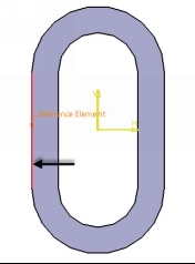
While creating a Pad feature, CATIA adds material in the direction normal to the sketch.
If you want to manually define the direction in which the material will be added, then click the More button on the Pad Definition dialog. Click in the Reference selection box and select a line.
 Shaft
Shaft
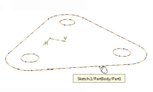
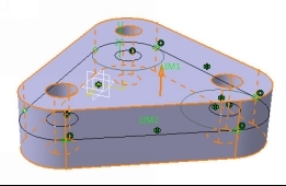
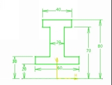
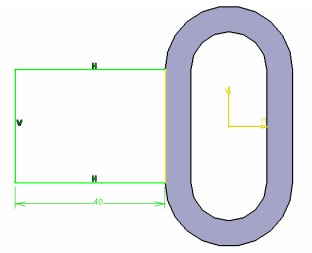
Revolving is the process of taking a two-dimensional profile and revolving it about a centerline to create a 3D geometry (shapes that are axially symmetric). While creating a sketch for the Shaft feature, it is important to think about the cross-sectional shape that will define the 3D geometry once it is revolved about an axis. For instance, the following geometry has a hole in the center.
This could be created with a separate Pocket or Hole feature. But in order to make that hole part of the Shaft feature, you need to sketch the axis of revolution so that it leaves a space between the profile and the axis.
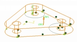
- After completing the sketch, activate the Shaft command (On the Profile toolbar, click the Shaft icon (or) click Insert > Sketch-Based Features > Shaft on the Menu).
- The sketch will be revolved by full 360 degrees.
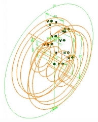
- If you want to enter an angle of revolution, type-in a value in the First Angle box.
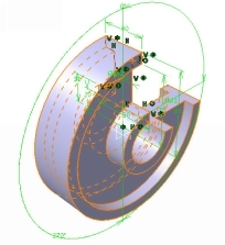
- On the dialog, click OK to complete the Shaft feature.
 Project 3D Elements
This command projects the edges of a 3D geometry onto a sketch plane.
- Activate the Sketcher Workbench by selecting a plane or model face.
- On the Operations toolbar, click 3D Geometry drop-down > Project 3D Elements (or) click I nsert > Operations > 3D Geometry > Project 3D Elements on the Menu.
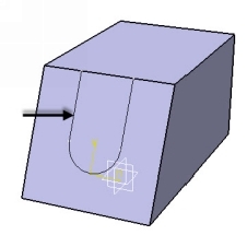
- Click on the edges of the model geometry to project them on to the sketch plane.
- Click OK on the Projection dialog.
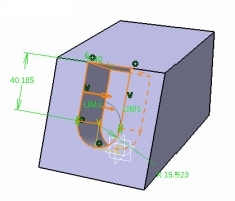
The projected element will be yellow in color and fully constrained. If you want to convert it into a normal sketch element, then right click on it and select Mark.object > Isolate .
- Complete the sketch and exit the workbench.
 The Pocket command
This command removes material from the geometry by extruding a sketch. It functions on the same lines of the Pad command.
- Draw a sketch on a plane or a model face.
- On the Sketch-Based Features toolbar, click the Pocket icon (or) click Insert > Sketch-Based Features > Pocket on the Menu.
- Select the sketch.
- On the Pocket Definition dialog, type-in a value in the Depth box and click Preview .
Font size:
Interval:
Bookmark:
Similar books «CATIA V5-6R2015 Basics Part II: Part Modeling by Tutorial Books»
Look at similar books to CATIA V5-6R2015 Basics Part II: Part Modeling by Tutorial Books. We have selected literature similar in name and meaning in the hope of providing readers with more options to find new, interesting, not yet read works.
Discussion, reviews of the book CATIA V5-6R2015 Basics Part II: Part Modeling by Tutorial Books and just readers' own opinions. Leave your comments, write what you think about the work, its meaning or the main characters. Specify what exactly you liked and what you didn't like, and why you think so.