HackingPhysics Journal
Vol.1, no 1
Jan 2020
Simple, Low-Cost and High-Performance Arduino Analog Measurements
Eric Bogatin
www.HackingPhysics.com
Copyright 2020 by Eric Bogatin
All rights reserved
The HackingPhysics Journal
A research report from the HackingPhysics Lab
A publication of Addie Rose Press
The HackingPhysics Journal is a periodic publication from the HackingPhysics Lab, published by Addie Rose Press.
Each issue focuses on a specific topic related to the combination of low-cost electronics and physics to empower the reader to dive into more detail exploring the world around us.
Each issue includes all the details about the hardware and software tools, enough of the principles to use them effectively, examples of science experiments anyone can do with these tools and some indications of where experimenters can explore further.
It is meant as the missing manual.
Table of Contents
Chapter 1. In This Issue
In this publication, I show you how to use both the built in 10-bit ADC and an external16-bit ADC with an Arduino Uno microcontroller board to master analog measurements.
All the instructions and sketches needed to measure, analyze, print, plot and save your measurements in a data file or directly in excel are included in this eBook.
In each sketch I provide, you can literally copy the sketch from this eBook, paste it into a blank sketch in the Arduino IDE and it will just work.
Here is an example of what is ahead for you in this publication:
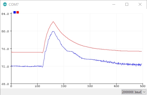
Figure 1.1. Measurements of the same TMP36 sensor at the same time by the 10-bit ADC (blue) and the 16-bit ADC (red).
Analog measurements are at the core of microcontroller applications. Afterall, most systems consist of a sensor, a controller and an actuator, with or without feedback between them.
Many sensors, which translate the physical world into an electrical quality, create an analog voltage signal. The way this gets into the controllers world of digital bits is with an analog to digital converter (ADC).
Built into the Atmega 328 microcontroller is a 10-bit ADC. Using the techniques illustrated in this publication, well see how to get the most out of this simple to use feature.
For many applications, 10-bit resolution, or the ability to measure 5 mV increments in voltage, is just fine. For others, higher resolution is a must.
After I illustrate how to get the most out of the 10-bit, built in ADC, Ill introduce you to the simplest to use, lowest cost 16-bit ADC available so you will quickly be taking measurements with a resolution which can be less than 20 uV and noise floor of less than 10 uV rms with averaging.
Using these two ADC devices, I show you in this publication how to:
Instantly measure, print and plot analog measurements with three lines of code
Increase the sample rate of the built in 10-bit ADC by more than a factor of 7
Average consecutive readings based on a fixed number of averages
Average consecutive readings over a time interval defined as an integral number of power line cycles to eliminate 60 Hz pick up
Calibrate the 10-bit ADC using the 3.3 V power rail on the Arduino board
Easily process the measurements to change the units based on a conversion factor
Use a low-cost 16-bit ADC and acquire data 3x faster than the default acquisition speed
Print the data to the serial monitor
Plot the data on the serial plotter as a scope or as a strip chart recorder
Data log the data into a text file
Print the data directly into excel and plot it in real time and save into an excel file
Chapter 2. Quick Start with the Built-in 10-bit ADC
If you are not familiar with some of the basic operations of the Arduino, check out the first book in the Saturday Afternoon Low-Cost Electronics Projects series, Arduinos Without Tears.
The Arduino communicates with the outside world with voltages. Digital voltages are written and read with the digital I/O pins. In addition, we can read analog voltages with the analog to digital converter (ADC).
These voltages can come from a variety of sources. The more interesting ones are from sensors that translate some aspect of the physical world into an electrical signal.
The ADC, which reads analog voltages, built into every Arduino board, is really easy to use. You can get started measuring your first voltages and print or plot your first voltage measurements in about one minute.
In this chapter, we will:
Measure a voltage as a digital level
Plot it on the serial plotter
Display the level value and when it was recorded on the serial printer
Copy this data from the serial monitor and paste it into excel
Plot it in excel
2.1 New hardware feature: the ADC
Built into every Arduino microcontroller is a special section of the chip that will measure the voltage on an input pin. This voltage is called an analog signal , as distinct from a digital signal.
Digital signals have only one of two values, a LOW or a HIGH, a logical 0 or a logical 1. In the Arduino Uno board, the voltage of a logical 1 signal is 5 V and the voltage of logical 0 signal is 0 V.
That's it. Those are our only choices in a digital signal.
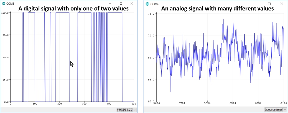
Analog signals can have almost any value within some range. To be read directly by an Arduino, the voltage level is limited to between 0 V and 5 V, but we can measure many different values between these limits. Figure 2.1 illustrates how the voltage of a digital and analog signal might vary over time.
Figure 2.1. An example of a digital signal (left) and an analog signal (right).
The analog voltage is measured and converted into digital information to then be interpreted by the Arduino, with the analog to digital converter (ADC) circuit built into the Arduino microcontroller chip.
The ADC in the Arduino Uno is able to measure a voltage with 10-bit resolution. This means the voltage is read and converted into 2 = 1024 different levels, ranging in value from 0 to 1023.
When we read a voltage value with an ADC, what the Arduino gives back to us is an integer corresponding to the level between 0 and 1023. These values correspond to an input voltage of about 0 to 5 V. This means each level corresponds to a voltage change of 5 V/1023 = 4.89 mV/ADU.
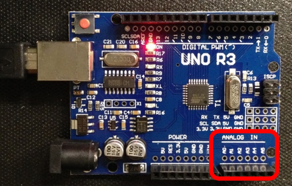
When the ADC measures a voltage on one of the specific analog input pins, labeled as A0 to A5, located in the lower right side of the board shown in Figure 2.2, it is always the difference in voltage between that pin and the ground pin on the Arduino board.
Figure 2.2. The Arduino Uno with the analog pins in the lower right of the board identified by the square.


