1.1 Power Electronics Systems
Over the past 30 years, the range of power electronics has expanded greatly. This has been caused by the extensive development of microelectronics in areas such as microprocessors, digital signal processors, memory circuits, complementary metal-oxide-semiconductors (CMOS), analog-to-digital (A/D) converters, digital-to-analog (D/A) converters, and power semiconductors, especially metal-oxide-semiconductor field-effect transistors (MOSFET) and insulated gate bipolar transistors (IGBT). Specifically, the development of power transistors has shifted the range of applications from a few amperes and hundreds of volts to several thousand amperes and a few kilovolts with a switching frequency measured in millions of hertz. Another area of application of power electronics circuits are micropower circuits and particularly energy harvesting circuits. Hence, power electronics circuits are now used everywhere, in power systems, industry, telecommunications, transportation, commerce, etc. They even exist in such modern popular devices as digital cameras, mobile phones, and portable media players. The background of power electronics is described by Mohan [], and many others.
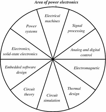
Power electronics is quite a difficult field of science and technology, requiring an extensive knowledge of related fields. These include areas such as: power systems, electrical machines, signal processing, analog and digital control, electronics, electromagnetic compatibility, solid-state electronics, embedded software design, circuit theory, circuit simulation, electromagnetic theory, thermal design, etc. These aspects are shown in Fig.. In order to produce properly functioning power electronics devices, all these aspects should be included. Often, the omission of one of these factors causes a system malfunction. This is due to the fact that a power electronics system converts energy and any errors are revealed in energy dissipation, which lead to the disruption or destruction of components. This book focuses attention on the aspects of digital signal processing applications in power electronics systems.
Fig. 1.1
Multidisciplinary nature of power electronics circuit
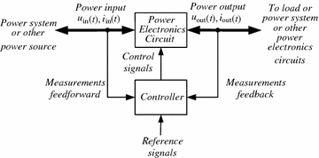
Fig. 1.2
A power electronics system
A simplified diagram of a power electronics system is shown in Fig.. The system makes the conversion of electric power from input to load. The power input is typically from a power system, electrochemical battery, solar cells or fuel cells, etc. The input power can be direct current (DC) or alternating current (AC): single phase, two phase, three phase, or more. The output power depends on the load. The power electronics circuit is monitored by a controller which compares the output power (feedback) and input power (feedforward) with the reference value needed to achieve the desired results. The controller can be designed to use either an analog or digital technique. Today the digital solution is most common, while the analog solution is reserved only for simple power electronics systems. The power flows through an electronics system from source to output. The output can be connected to a load or to an other power system or to other power electronics circuits, etc. However, the power electronics circuit may be reversed and then the energy can flow from output to source.
1.2 Digital Control Circuits for Power Electronics Systems
The most common power electronics system element is the inverter. Single- or three-phase (even more in multi-phase or in multilevel devices) inverters are frequently used parts of power electronics systems, in such devices as: AC and DC motor drives, uninterruptible power supplies, harmonic compensators, DC power supplies, controlled rectifiers, AC and DC power transmission systems, smart grid, etc.
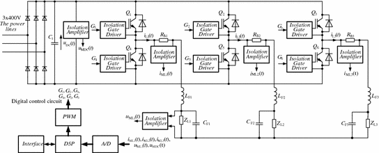
Fig. 1.3
Exemplary three-phase inverter with digital controller
A simplified block diagram of an exemplary three-phase inverter with digital controller is shown in Fig.. The inverter consists of six power IGBT transistors

, controlled by drivers with galvanic isolation. This galvanic isolation should have low input-to-output capacitance and should be highly resistant to a high output voltage slew rate, in the range 1020 kV/s. One of the inverter legs consists of two transistors

and

, which are connected to the load

through the LC low-pass filter (

) for suppressing pulse width modulation (PWM) components. The inverter is controlled by a digital signal processor (DSP) which performs the control algorithm. The control DSP function can be realized using one of several devices: general purpose microprocessors, microcontrollers, advanced microprocessors and microcontrollers, digital signal processors and programmable digital devices, etc. As with transistor control signals, analog signals representing currents and voltages are galvanically isolated too. The analog signals are converted into the digital form by an A/D converter. The algorithm controls the output signal value using controlling output transistors by pulses generated by the same kind of pulse modulator. In the early days of digital control circuits, the control algorithms were very simple and represented only digital versions of analog control circuits with a single sampling frequency. Over time, control algorithms have turned into highly advanced and more complicated solutions. Currently, control circuits designed to increase signal dynamic range use a few sampling frequencies. Digital circuits using different sampling rates are called multirate digital circuits.



 , controlled by drivers with galvanic isolation. This galvanic isolation should have low input-to-output capacitance and should be highly resistant to a high output voltage slew rate, in the range 1020 kV/s. One of the inverter legs consists of two transistors
  and
and  , which are connected to the load
  through the LC low-pass filter (
  ) for suppressing pulse width modulation (PWM) components. The inverter is controlled by a digital signal processor (DSP) which performs the control algorithm. The control DSP function can be realized using one of several devices: general purpose microprocessors, microcontrollers, advanced microprocessors and microcontrollers, digital signal processors and programmable digital devices, etc. As with transistor control signals, analog signals representing currents and voltages are galvanically isolated too. The analog signals are converted into the digital form by an A/D converter. The algorithm controls the output signal value using controlling output transistors by pulses generated by the same kind of pulse modulator. In the early days of digital control circuits, the control algorithms were very simple and represented only digital versions of analog control circuits with a single sampling frequency. Over time, control algorithms have turned into highly advanced and more complicated solutions. Currently, control circuits designed to increase signal dynamic range use a few sampling frequencies. Digital circuits using different sampling rates are called multirate digital circuits.