N Ahlhelm - An Introduction to High Reliability Soldering and Circuit Board Repair
Here you can read online N Ahlhelm - An Introduction to High Reliability Soldering and Circuit Board Repair full text of the book (entire story) in english for free. Download pdf and epub, get meaning, cover and reviews about this ebook. year: 2013, publisher: CreateSpace Independent Publishing Platform, genre: Computer. Description of the work, (preface) as well as reviews are available. Best literature library LitArk.com created for fans of good reading and offers a wide selection of genres:
Romance novel
Science fiction
Adventure
Detective
Science
History
Home and family
Prose
Art
Politics
Computer
Non-fiction
Religion
Business
Children
Humor
Choose a favorite category and find really read worthwhile books. Enjoy immersion in the world of imagination, feel the emotions of the characters or learn something new for yourself, make an fascinating discovery.

An Introduction to High Reliability Soldering and Circuit Board Repair: summary, description and annotation
We offer to read an annotation, description, summary or preface (depends on what the author of the book "An Introduction to High Reliability Soldering and Circuit Board Repair" wrote himself). If you haven't found the necessary information about the book — write in the comments, we will try to find it.
N Ahlhelm: author's other books
Who wrote An Introduction to High Reliability Soldering and Circuit Board Repair? Find out the surname, the name of the author of the book and a list of all author's works by series.

An Introduction to High Reliability Soldering and Circuit Board Repair — read online for free the complete book (whole text) full work
Below is the text of the book, divided by pages. System saving the place of the last page read, allows you to conveniently read the book "An Introduction to High Reliability Soldering and Circuit Board Repair" online for free, without having to search again every time where you left off. Put a bookmark, and you can go to the page where you finished reading at any time.
Font size:
Interval:
Bookmark:
No part of this book may be reproduced in any form or transmitted by any means without the writtenpermission of the author.
No patent liability is assumed with respect to the use of the information contained herein. Everyprecaution has been taken in the preparation of this book. The publisher and author assume noresponsibility for errors or omissions. Neither is any liability assumed for damage resulting from the useof the information contained herein.
This book is an introduction to the techniques of electronic repair and, to a lesser extent,fabrication. Electronic repair in this text is directed only at soldering and board repair, nottroubleshooting. And, as with all texts dealing with technology, the book is not inclusive of everymethod available to the technician. No prior knowledge of the operation of electronic components orrepair expertise is needed. Basic soldering tools are used as much as possible to perform the work.Unfortunately, some specialized tools will have to be used for board repairs and the installation ofsurface mount components.
This edition has minor changes to include: metric wire gages, standards are now listed in metricalso, improved some images, and revision of a few confusing questions.
The standard used throughout the text for all soldering is IPC (Association ConnectingElectronics Industries, formerly the Institute of Interconnecting and Packaging Electronic Circuits) J-STD001D dated February 2005. It is the accepted model used by the American National Standards Instituteas well as the Department of Defense. Repair standards should meet IPC-7711/7721.
Listed here are some of the safety precautions that should be observed at all times.Additionally, follow the procedures established by Federal and State regulations and your employer.
1) Know your tools and supplies.
2) Inspect your tools to make sure they are in perfect working order.
3) Wear eye or face protection.
4) Work in a well-ventilated area and/or have fume extraction devices operating if available.
5) Wash your hands after working with solder, particularly those containing lead.
6) Avoid wearing loose jewelry or clothing ties are out!
7) Wear long sleeves and pants this prevents burns if solder should splatter.
8) No open toed shoes same reason as six. You may also be working with heavy objects.
9) Do not touch the irons tip even if you think it is cold.
10) Keep your work area clean and organized.
11) Make sure the iron never touches the power cord.
12) Ergonomics must be considered. Make sure the chair is in the correct position, the work
table is at a proper height, and lighting is sufficient.
13) Solder on fire resistant surfaces.
14) Do not overload your electrical outlets.
15) Shut your equipment down when not in use.
Chapter 1, The Basics.
Wire Gage .7
Other Conductors
Waveguides ..13
Chapter 2, Standards: Wires and Splices
Wire Connections
Crimping and Splicing Tools ....26
Solder Splicing Sleeves.....28
Coaxial Cable Connectors ..28
Chapter 3, Irons, Solders, and Fluxes
Mass, Time, and Pressure
Chapter 4, Wire Connections and Connectors
Tinning ....57
Soldering Wires Splices
Sealing the Tap Splice...73
Chapter 5, Printed Circuit Boards
Boards types ......76
Making a Circuit
Chapter 6, Installation and Removal of
Through-Hole Components
Before Component Installation
Mounting an Unsupported
Through-Hole Component ....96
Through-Hole Component Removal
Conformal Coatings..........103
Chapter 7, Removal and Installation of
Surface Mount Components
Installation and removal of Chip Resistors, MELFs,
Chip Capacitors and SOTs
Installation of QFPs, PLCCs, and SOICs
Re-Balling Using Solder Paste130
Re-Balling Using Solder Spheres ...131
Chapter 8, Track, Pad, and Board Repairs
Damaged or Missing Tracks
Lifted Pads and Tracks .....134Broken or Missing Tracks
Using a Track Frame without Adhesive ..134
Using a Track Frame with Adhesive ..140
Busbars ....142
Staples ...143
Jumper Wires.144
Replacing Large Sections of Damaged PCBs
Small Repairs (1/2 or Less): Repair Does
Damage Extends Through the Board.151
Replacement of Large Sections of a PCB ..152
A wire must be electrically transparent to the circuit in which it functions. By electrically transparent wemean that it must not affect the current or voltage of the circuit. So, how can a wire affect current orvoltage in a poor design? How will a wire react to different frequencies? How does a wire function in a proper design? Finally, if you have to make a repair to a wire, how do you make it as mechanically strongas the original and make it electrically sound?
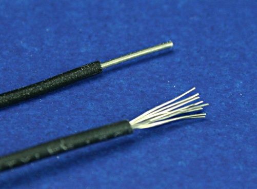 Figure 1-1Solid and Stranded wires.
 The most commonly used conductor is the wire. It comes intwo varieties, Stranded and Solid. The material from whichthey are usually made is copper (because of its very lowresistance and reasonable cost). Figure 1-1 shows both a solidconductor and a stranded conductor. Each type of wire hascertain benefits and shortcomings. The solid wire is easier tomanufacture, it is only a single strand. Its disadvantage is thatsolid wire is not intended to be used in areas where it must be
Conductance Compared toMaterialSilver
Silver
Copper
Gold
Aluminum
Iron
Tin
Carbon0.05
bent regularly. This wire may be bent only a few timesbefore it breaks. Stranded wire, on the other hand, ismore costly to manufacture: a certain number ofstrands of a given size must be wound together toachieve the desired diameter. It has the advantage ofbeing more resilient than a solid wire (of similar size)when wires must be bent. It can be flexed more often without damage.
Copper, as mentioned earlier, is an excellentconductor. The resistance of copper per foot isextremely low, less than 0.077 ohms for a wire havinga diameter of 0.012. This makes it largely transparent electrically since it does not affect current muchor create voltage drops. As the size of the wire increases, this resistance value continues to drop. Table1-1 shows the relative conductance of copper as compared to the idealmaterial, silver. Silver mightbe the best conductor available, but it is too costly for most consumer electronics. Gold is also listed.You can see that it has 78% of the conductance of silver. Aluminum is rarely, if ever, used in circuits.Because of its considerable resistance, heat tends to build up along its length. Aluminum wire was usedin residential electrical systems during the 1970s and was responsible for several home fires because ofits high resistance.
The diameter of a conductor has to be sized to the application, some circuits require morecurrent and voltage than others. In the United States, the American Wire Gauge (AWG) standard is usedas a measure of conductor diameter. Table 1-2 lists some of the common sizes used. Mostmanufacturers of electronics use the even numbered gauges so many of the odd number values havebeen omitted.
MetricDiameterArea inAWGWire3(mm2)in milscmils1OhmsFusePerMaximumRating1000 FtCurrent*s2
403.1459.8910.093.54312.555
383.96515.7210.1124.40919.44
365250.145.51230.379
346.30539.7530.187.08650.218
327.9563.2030.259.84296.872
3010.025100.50.3111.8139.236
Font size:
Interval:
Bookmark:
Similar books «An Introduction to High Reliability Soldering and Circuit Board Repair»
Look at similar books to An Introduction to High Reliability Soldering and Circuit Board Repair. We have selected literature similar in name and meaning in the hope of providing readers with more options to find new, interesting, not yet read works.
Discussion, reviews of the book An Introduction to High Reliability Soldering and Circuit Board Repair and just readers' own opinions. Leave your comments, write what you think about the work, its meaning or the main characters. Specify what exactly you liked and what you didn't like, and why you think so.