PIC Communication and PIC Microcontroller Electric circuit best Projects Handson
SPI Communication, 4x4 Matrix Keypad, Digital Alarm Clock , Stepper Motor, Digital Clock , I2C Communication, Advanced Thermometer, Interfacing Joystick etc...,
Anbazhagan K
Copyright 2020 Anbazhagan K
All rights reserved
The characters and events portrayed in this book are fictitious. Any similarity to real persons, living or dead, is coincidental and not intended by the author.
No part of this book may be reproduced, or stored in a retrieval system, or transmitted in any form or by any means, electronic, mechanical, photocopying, recording, or otherwise, without express written permission of the publisher.
Contents
Acknowledgments
The writer might want to recognize the diligent work of the article group in assembling this book. He might likewise want to recognize the diligent work of the Raspberry Pi Foundation and the Arduino bunch for assembling items and networks that help to make the Internet of Things increasingly open to the overall population. Yahoo for the democratization of
innovation!
Introduction
The Internet of Things (IOT) is a perplexing idea comprised of numerous PCs and numerous correspondence ways. Some IOT gadgets are associated with the Internet and some are most certainly not. Some IOT gadgets structure swarms that convey among themselves. Some are intended for a solitary reason, while some are increasingly universally useful PCs. This book is intended to demonstrate to you the IOT from the back to front. By structure IOT gadgets, the per user will comprehend the essential ideas and will almost certainly develop utilizing the rudiments to make his or her very own IOT applications. These included ventures will tell the per user the best way to assemble their very own IOT ventures and to develop the models appeared. The significance of Computer Security in IOT gadgets is additionally talked about and different systems for protecting the IOT from unapproved clients or programmers. The most significant takeaway from this book is in structure the tasks yourself.
1. Transfer Interfacing with PIC Microcontroller
In this task we will interface a Relay with PIC Microcontroller PIC16F877A. Hand-off is a mechanical gadget to manage high voltage, high current machines 'ON' or 'OFF' from lower voltage levels. Transfer gives separation between two voltage levels and it is by and large use to control AC apparatuses. From mechanical to Solid state transfers, there are different kind of transfers are accessible in hardware. In this venture we will utilize mechanical hand-off.
In this venture we will do the accompanying things-
- We will Interface a switch for contribution from client.
- Control a 220V AC bulb with 5V transfer.
- To manage the transfer we will utilize BC547 Negative Positive Negative transistor along with the transistor will be managed from the PIC16F877A. A drove will tell the hand-off ON or OFF condition.
On the off chance that you are new to PIC Microcontroller, at that point start with Getting Started with PIC Microcontroller.
Segment Necessary:
- Wires for associating the parts.
- 5V Adapter or any 5V power source with at any rate 200mA current capacities.
Transfer and its Working:
Transfer works same as run of the mill switch. Mechanical transfers utilize transitory magnet produced using electromagnetic loop. At the point when we give enough current over this loop, it became invigorated and pulls an arm. Because of that the circuit associated over the hand-off can be shut or open. The Input along with Output don't have any electrical associations and in this way it disconnects information and yield. Become familiar with hand-off and its developments here.
Transfers can be found in various voltage ranges like 5V, 6V, 12V, 18V along with etc. In this venture we will utilize 5V transfer as our working voltage is 5 Volts here. This 5V cubic hand-off is skilled to switch 7A load at 240VAC or 10A burden at 110VAC. Anyway rather that tremendous burden, we will utilize a 220VAC bulb and switch it utilizing the hand-off.
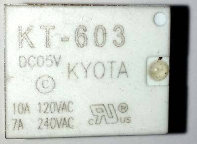
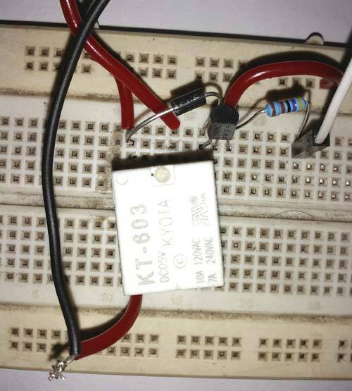
This is the 5V Relay we are utilizing in this undertaking. The present rating is unmistakably indicated for 2 voltage levels, 10A at 120VAC along with 7A at 240VAC. We have to associate burden over the transfer not exactly the predetermined rating.
5V Cubic Relay
This hand-off has 5 pins. On the off chance that we view the pinout we can view-
The L1 and L2 is the interior electromagnetic curl's pin. We have to control these 2 pins for turning the transfer 'ON' or 'OFF'. Next three pins are POLE, NO and NC. The shaft is associated with the inside metal plate which changes its association when the hand-off turns on. In ordinary condition, POLE is shorted with NC. NC represents regularly associated. At the point when the transfer turns on, the shaft changes its position and become associated with the NO. NO represents Normally Open.
In our circuit, we have made the hand-off association with transistor and diode. Transfer with transistor and diode is accessible in advertise as Relay Module, so when you use Relay Module you don't have to associate its driver circuit (Transistor and diode).
Transfer is utilized in all the Home Automation Projects to control the AC Home Appliances.
Circuit Diagram:
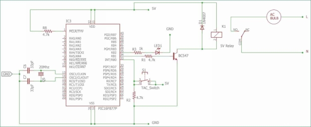
Complete circuit for associating Relay with PIC Microcontroller is given beneath:
In the above schematic pic16F877A is utilized, where on the port B the LED and Transistor is associated, which is additionally controlled utilizing the TAC switch at RBO. The R1 give predisposition current to the transistor. R2 is a draw down resistor, utilized across material switch. It will give rationale 0 when the switch isn't squeezed. The 1N4007 is a clip diode, utilized for the hand-off's electromagnetic curl. At the point when the hand-off will killed, there are chances for high voltage spikes and the diode will smother it. The transistor is need for driving the transfer as it needs more than 50mA of current, that the microcontroller can't give. We can likewise utilize ULN2003 rather the transistor, it is a more astute decision if more than a few transfers are required for the application, check the Relay module circuit. The LED across port RB2 will tell "transfer is on".
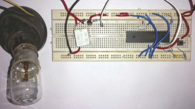
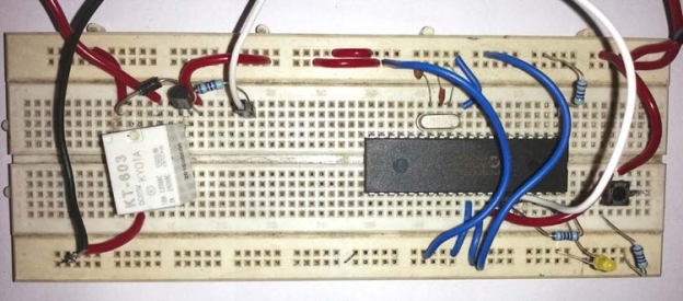
The last circuit will resemble this-


