Tricky Circuit projects with programmed Level handson
Programmed Staircase Lights, IR Remote, Tune or Sound Generator, Movement Detector, Vehicle Tracking, Line Follower Robot, Controlling Brightness of LED etc...,
Anbazhagan K
Copyright 2020 Anbazhagan K
All rights reserved
The characters and events portrayed in this book are fictitious. Any similarity to real persons, living or dead, is coincidental and not intended by the author.
No part of this book may be reproduced, or stored in a retrieval system, or transmitted in any form or by any means, electronic, mechanical, photocopying, recording, or otherwise, without express written permission of the publisher.
Contents
Acknowledgments
The writer might want to recognize the diligent work of the article group in assembling this book. He might likewise want to recognize the diligent work of the Raspberry Pi Foundation and the Arduino bunch for assembling items and networks that help to make the Internet of Things increasingly open to the overall population. Yahoo for the democratization of innovation!
Introduction
The Internet of Things (IOT) is a perplexing idea comprised of numerous PCs and numerous correspondence ways. Some IOT gadgets are associated with the Internet and some are most certainly not. Some IOT gadgets structure swarms that convey among themselves. Some are intended for a solitary reason, while some are increasingly universally useful PCs. This book is intended to demonstrate to you the IOT from the back to front. By structure IOT gadgets, the per user will comprehend the essential ideas and will almost certainly develop utilizing the rudiments to make his or her very own IOT applications. These included ventures will tell the per user the best way to assemble their very own IOT ventures and to develop the models appeared. The significance of Computer Security in IOT gadgets is additionally talked about and different systems for protecting the IOT from unapproved clients or programmers. The most significant takeaway from this book is in structure the tasks yourself.
1. PDA Charger Circuit
Cell phones by and large accuse of 5v controlled DC supply, so essentially we are going to manufacture a 5v directed DC supply from 220 AC. This DC supply is used to charge mobiles just as the force hotspot for computerized circuits, breadboard circuits, ICs, microcontrollers and so forth.
You can likewise assemble 6V DC, 9V, 12V, 15V and so forth by utilizing legitimate transformer, capacitor and voltage controller. The fundamental idea continues as before, you need to mastermind a warmth sink for higher voltage and current.
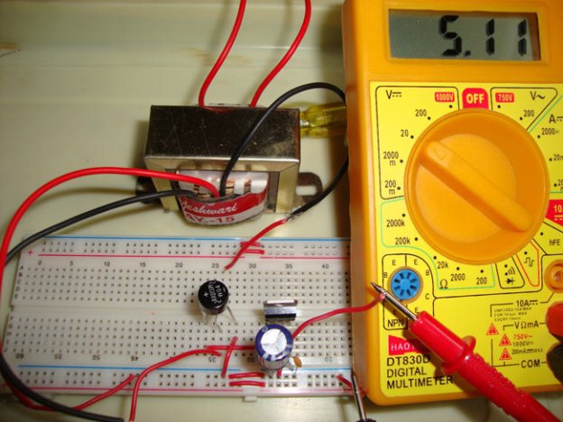
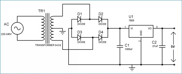
This circuit principally comprises a stage down Transformer, a Full wave connect rectifier and a 5V voltage controller IC (7805). We can separate this circuit into 4 sections: (1) Step down AC voltage (2) Rectification (3) Filtration (4) Voltage Regulation.
1. Venture down AC voltage
As we are changing over 220V AC into a 5V DC, first we need a stage down transformer to lessen such high voltage. We have utilized 9-0-9 1A step-down transformer, which convert 220V AC to 9V AC. In transformer there are essential and auxiliary loops which venture up otherwise step down the voltage as indicated by the no of turn in the curls.
Determination of legitimate transformer is significant. Current rating relies on the Current necessity of Load (circuit which will utilize the produce DC). The voltage rating ought to be more than the necessary voltage. Means in case we need 5V DC, transformer ought to in any event have a rating of 7V, in light of the fact that voltage controller IC 7805 at any rate need 2V more for example 7V to give a 5V voltage.
2. Amendment
Amendment is the way bring closer expelling the negative piece of the Alternate Current (AC), thus creating the fractional DC. This can be accomplished by utilizing 4 diodes. Diodes just permit current to stream one way. In first half pattern of AC diode D2 along with D3 are forward one-sided and D1 along with D4 are turned around one-sided, and in the subsequent half cycle (negative half) Diode D1 along with D4 are forward one-sided and D2 along with D3 are switched one-sided. This Combination changes over the negative half cycle into positive.
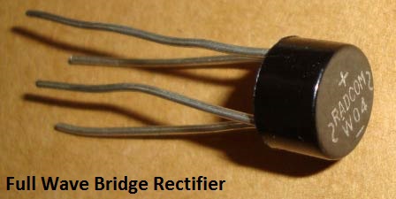
A full wave connect rectifier segment is accessible in the market, which comprise that mix of 4 diode inside. Here we have utilized this segment.
3. Filtration
The yield after the Rectification is definitely not a legitimate DC, it is swaying yield and has an exceptionally high wave factor. We needn't bother with that throbbing yield, for this we use Capacitor. Capacitor charge till the waveform goes to its pinnacle and release into Load circuit when waveform goes low. So when yield is going low, capacitor keeps up the make the most voltage supply into the Load circuit, henceforth making the DC. Presently how the evaluated of this channel capacitor must be determined. Here is the formulae:
C = I * t/V
C= capacitance to be determined
I= Max yield current (suppose 500mA)
t= 10ms,
We will get wave of 100Hz recurrence in the wake of changing over 50Hz Alternating Current into Direct Current, through full wave connect rectifier. As the negative piece of the beat is changed over into positive, one heartbeat will be tallied two. So the time frame will be 1/100= .01 Second= 10ms
V = Peak voltage voltage given to voltage controller IC (+2 more than appraised implies 5+2=7)
9-0-9 is the RMS evaluation of changes so top voltage is Vrms * 1.414= 9* 1.414= 12.73v
Presently 1.4v will be dropped on 2 diodes (0.7 per diode) as 2 will be forward one-sided for half wave.
So 12.73 1.4 = 11.33v
At the point when capacitor releases into load circuit, it must give 7v to 7805 IC to work so at long last V is:
V = 11.33 7= 4.33v
So now C = I * t/V
C = 500mA * 10ms/4.33 = .5 * .01/4.33 = 1154uF ~ 1000uF
4. Voltage Regulation
A voltage controller IC 7805 is utilized to give a managed 5v DC. Info voltage ought to be 2volts more than the evaluated yield voltage for appropriate working of IC, implies at any rate 7v is required, in case it can work in input voltage scope of 7-20V. Voltage controllers have all the hardware inside it to give an appropriate managed DC. Capacitor of 0.01uF ought to be associated with the produce of the 7805 to take out the clamor, delivered by transient changes in voltage.
Here is the finished circuit graph for PDA charger circuit:


