Jakob Andreas Brentzen , Jens Gravesen , Franois Anton and Henrik Aans Guide to Computational Geometry Processing 2012 Foundations, Algorithms, and Methods 10.1007/978-1-4471-4075-7_1 Springer-Verlag London 2012
1. Introduction
Abstract
This introductory chapter motivates the book through a discussion of the many sources and applications of geometric data.
Small to medium sized objects can be captured with a variety of optical acquisition techniques, such as laser scanning, structured light scanning, and time of flight cameras. There are many uses of optical acquisition, and number of these are medical in nature: for instance, laser scanning has emerged as an important part of in-the-ear hearing aid manufacturing.
At the other end of the scale spectrum, airborne laser scanning allows us to build digital terrain models and ultimately city models. Finally, a lot of geometric data are still produced manually through the use of CAD software.
Going through each topic, we discuss what geometry processing algorithms are pertinent and refer the reader to the chapters where these algorithms are discussed in greater detail.
Invoking Moores law and the long term exponential growth of computing power as the underlying reasons for why a particular research field has emerged is perhaps a bit of a clich. Nevertheless, we cannot get around it here. Computational geometry processing is about practical algorithms that operate on geometric data sets, and these data sets tend to be rather large if they are to be useful. Processing a big polygonal mesh, say a triangulated terrain, an isosurface from a medical volume, or a laser scanned object, would generally not be feasible given a PC from the early 1980s with its limited computational power and a hard disk of around 10 MB. Even in the late 1990s, large geometric data sets might require numerous hard disks. For instance, the raw scans of Michaelangelos David as carried out by Marc Levoy and his students during the Digital Michelangelo project [] required 32 GB of spacemore than a typical hard disk at the time. However, since then the world has seen not only a sharp decrease in the price of computation and storage but also a proliferation of equipment for acquiring digital models of 3D shapes, and in 2003 also the Symposium on Geometry Processing which was founded by Leif Kobbelt.
Due to its practical nature, geometry processing is a research field which has strong ties to numerous other fields. First of all, computer graphics and computer vision are probably the fields that have contributed most to geometry processing. However, many researchers and practitioner in other fields confront problems of a geometric nature and have at their disposal apparatus which can measure 3D geometric data. The first task is to convert these data to a useable form. This is often (but not always) a triangle mesh. Next, since any type of measurement is fraught with error, we need algorithms for removing noise from the acquired objects. Typically, acquired 3D models also contain a great deal of redundancy, and algorithms for geometry compression or simplification are also important topics in geometry processing. Moreover, we need tools for transmission, editing, synthesis, visualization, and parametrization; and, of course, this is clearly not an exhaustive list. Painting with rather broad strokes, we see the goal of geometry processing as to provide the tools needed in order to analyze geometric data in order to answer questions about the real world or to transform it into a form where it can be used as a digital prototype or as digital content for, e.g., geographical information systems, virtual or augmented reality, or entertainment purposes.
The goal of this chapter is to present a selection of the domains in which geometry processing is used. During this overview, we will also discuss methods for acquiring the geometric data and refer to the chapters where we discuss the topics in detail.
1.1 From Optical Scanning to 3D Model
Acquisition of 3D data can be done in a wide variety of ways. For instance, a touch probe allows a user to interactively touch an object at various locations. The probe is connected to a stationary base via an articulated arm. Knowing the lengths and angles of this arm, we can compute the position of the tip and hence a point on the object. Clearly, this is a laborious process. There are also automated mechanical procedures for acquisition, but due to the speed and relative ease with which it can be implemented, optical scanning has emerged as the most used method for creating digital 3D models from physical objects.
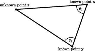
Almost all optical scanning procedures are based on optical triangulation , cf. Fig. : From the relative positions and orientations of the two cameras combined with the positions in the images of the observed points, we can compute the two angles 1 and 2 and, consequently, the position of the unknown point z . Expressed differently: given a camera of known orientation and position, a point in the image produced by the camera corresponds to a line in space. Thus, if we observe the same 3D point in two cameras, we can find the location of that 3D point as the intersection of two lines. Namely, the lines that correspond to the images of the 3D point in each of the two cameras.
Fig. 1.1
An illustration of basic optical triangulation. Assume that unknown point z is observed from points x and y , of which we know the positions. If we also know the angles 1 and 2, then point z s position can be determined by simple trigonometry. The observations of point z in points x and y can e.g. be made by cameras or photogrammetrists on hilltops
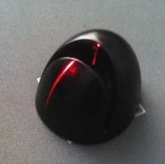
Unfortunately, it is not easy to find points in two images that we can say with certainty to correspond to the same 3D point. This is why active scanners are often used. In an active scanner a light source is used in place of one of the cameras. For instance, we can use a laser beam. Clearly, a laser beam also corresponds to a line in space, and it is very easy to detect a laser dot in the image produced by a camera thus obtaining the intersecting line. In actual practice, one generally uses a laser, which emits a planar sheet of light. Since line plane intersection is also unique, this is not much of a constraint. In fact, it allows us to trace a curve on the scanned object in one go. A laser plane shone onto a surface is illustrated in Fig.. Finally, by projecting a structured pattern of light onto an object with a projector, it can be made much easier to find correspondences. This is known as structured light scanning.
Fig. 1.2
To help establish correspondences between images, laser light can e.g. be shone on the object, as illustrated here
Another optical technology for 3D optical acquisition is time of flight (ToF), cf. Fig.. Here a light pulse (or an array of light pulses) is emitted, and the time it takes for these light pulses to return is measured. Typically, this is done by measuring the difference in phase between the outgoing and the returning light. Note that this modality directly provides a depth value per pixel.

