A CKNOWLEDGMENTS
This book would not have been possible without a lot of help through the years. Many of the relationships Ive made both personally and professionally have been fuel to keep me going over the years and opened the doors that made this all possible.
I would like to thank the people at SCT, Mustang Dynamometer, Dynojet Research, HPTuners, Engine Controls and Monitoring, Mr. Gasket, F.A.S.T., Vortech Engineering, MRT Racing, SiemensVDO, Magnuson Products, Diablosport, MSD, Autronic, Trick Flow Specialties, Ford, and Mopar for their recent help and opportunities to challenge myself over the years.
Nate Tovey, my photographer for this book, put in plenty of long hours alongside me when it counted. Thanks buddy, we made it happen.
Andrea, my wife, put in just as many long hours as I ever did. You stood by me while I chased my dream and earned my experience the hard way: one long night at the shop after another. Not only have you gracefully put up with my obsessions, but you did it with a smile. Youve always been there for me and helped me keep my focus. What more could a guy ask for?
Dave and Jay, if only you could join me now for the good times. Godspeed and God bless.
Greg Banish
APPENDIX A
F ORD T UNING
The Ford Mustang is arguably the most popular vehicle for the do-it-yourself tuner. Ford refers to its PCM as an EEC, or electronic engine control. Starting with the 1988 California specification, and 1989 50-state versions, the Mustang has been equipped with a mass air, sequential EFI system. Other truck and passenger car applications soon followed suit. Various iterations of the EEC have been released with increasing clock speed and capabilities. The EEC-IV systems used on the 19891995 OBD-I vehicles were extremely well received by the aftermarket community for their ease of programming and relatively simple control strategy. The mass air based system allowed a large amount of flexibility and ability to adapt at elevated power levels. With a scaled MAF and larger injectors, it was not uncommon to see unmodified EECs supporting over 600 hp. Although drivability was not ideal, the engine operation was acceptable to the performance enthusiast who valued quarter-mile ETs over street manners. The advent of custom tuning software for these EECs allowed experienced calibrators the opportunity to deliver tremendous horsepower and excellent street manners with the stock EEC hardware. Programmable chips were designed as modules that could be plugged into the J3 service port opposite the wiring harness on the EEC to hold new operational code for the EEC. When the EEC is booted, the J3 port is examined for data. If an aftermarket module with a valid program is plugged in, the EEC reads the file on it and operates entirely based upon data stored on the new module. If no module is present, the EEC reverts to the program hard coded onto the stock board from the factory.
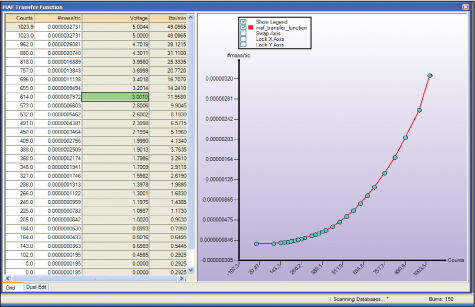
This screen shot from the SCT Advantage software shows the MAF transfer function of a 2001 Mustang Cobra. The EEC actually processes in A/D (analog to digital) counts, but SCT has done the math to show the calibrator actual voltage in the table as well for comparison.
The 1996 Mustang brought in the era of modular engines and OBD-II controls with the EEC-V. Software companies responded with programming tools that offered the same flexibility on the newer EEC-V with the benefit of the finer control strategy from Ford available to the aftermarket tuner as well. The EEC-V family retained the popular J3 port available for aftermarket chip interface, but could now also be flash programmed via the OBD port under the dash. The 2002 EEC-V added another twist with an internal limit to the maximum calculated MAF rate that was reduced to a little over 1,700 kg/hr. Since many supercharged applications can exceed this, scaling of the MAF/injector size/engine displacement became necessary at high power levels on the later versions.
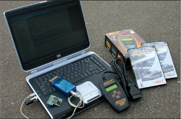
The SCT tuning package puts everything at your fingertips to modify and datalog almost any modern Ford vehicle. (Nate Tovey)
In 2005, Mustang moved to a new family of engine controller known internally as the Oak family, with variants spreading across the entire product line. This new processor remains mass air based, but now includes torque-based ETC control. Modifications are still possible, but the torque-based ETC strategy poses a significant challenge to inexperienced calibrators who wish to drastically increase engine power. The trusty J3 port on this processor is gone as well. The only way to change calibration data is by flash programming. To further complicate things, the new CAN (controller area network) protocol is used for communication rather than the older KWP (key word protocol) as seen in earlier OBD-II EECs. This limits access to scan tools and programmers that have been updated with the newer CAN communication strategy.
Ford EECs convert most voltage inputs from sensors (MAF, TPS, etc.) into an A/D count before actual processing. Some software packages normalize this to only show voltage values in the editor; others leave it as counts. The actual scaling depends upon the clock speed of the processor being used, but it always works out such that 0 to 5 v reference signals become 0 to 1,023 A/D counts. Clock speed of the processor determines the sampling rate, so time-based sensor inputs such as MAF must be corrected before processing. Many actual raw MAF transfer functions are listed pound mass per clock tick rather than pounds per hour, so this can lead to confusion when attempting to copy a MAF transfer function from one model into another if the normalization is not correct.
The Ford EEC-IV/V uses a Hitachi-manufactured MAF sensor with a heated wire element. This design provides a temperature-compensated mass flow measurement directly to the processor. The post in the center of the MAF helps to reduce the effect of standing waves in the inlet tract on actual MAF measurement. Actual output of this MAF sensor ranges from 0 to 5 v, with a 0 lb/hr= 0 v intercept. The EEC only recognizes a maximum input value of 5 v, even though most sensors continue to increase output voltage with respect to flow all the way up to battery voltage. To prevent pegging the EECs MAF input, the range of the sensor being used should be selected to match the intended maximum engine airflow rate. Many stock calibrations also limit the maximum recognized MAF input to about 4.7 v to account for build tolerances and voltage drift. Since the slope of the MAF transfer function is so steep in this range, the addition of ~0.2 v worth of range (4.9 v max) can usually safely allow for more measurement capacity with the same hardware.
The later 2002 and up EEC-V controllers employ another unique variable Ford calls max air charge multiplier that must be changed when adding a supercharger. This variable limits the effective maximum load calculations. Most naturally aspirated applications have this set to 0.9. Changing this to 1.9 (the upper limit in the software) allows the EEC to properly compute loads well beyond 100%. This is also sometimes accompanied by the variable anticipated air charge multiplier which should be set slightly lower at approximately 1.8.
Over the years, many of the OE parameters have become accessible to the public. Companies like Superchips Custom Tuning and Diablosport offer excellent calibration tools that display all the essential calibration parameters in a friendly Windows-based environment. These software and hardware packages supply everything needed to start from the OEM calibration and change any scalars, functions, or tables needed to accommodate the performance enthusiasts needs. The appropriate starting file is selected by noting the catch code marked on both the EEC and the inside of the passenger doorjamb. Once this file is opened up in the editor, changes can be made and saved as a new tuning file. This new tuning file can then be either flashed to a chip to be plugged into the external J3 port of the EEC (the opening with an exposed edge connector opposite of the wiring harness) or stored in a handheld programmer for direct EEC reflashing via the OBD-II port under the dash. Lets look at a couple of specific examples:


