The complete beginners guide on everything you need to know about your digital multimeter for beginners
Phil C. Davidson
Chapter one
How to Measure Voltage, Current, and Resistance using a Multimeter
What is the purpose of a digital multimeter?
Professionals in a variety of sectors employ multimeters, such as industrial maintenance and testing, research, appliance repair, and electrical installation. A digital multimeter, or DMM, is a useful test equipment for home and DIY projects. The instrument can be used to check voltage, current, and resistance as well as measure voltage, current, and resistance.
The voltage of the batteries
Electrics and electronics in automobiles
Cable and power cord continuity
Electrical equipment and appliances in the home
Fuses
What Do Volts, Amps, and Ohms Really Mean?
We must first become familiar with the quantities we will be measuring before learning how to use a multimeter. A voltage source, which can also be coupled to a load, is the most fundamental circuit we'll see. A battery, DC power supply, or mains power supply could be used as the voltage source. There are many different forms of loads, but they are typically devices like lamps, motors, or electronic resistors. A schematic is a diagram that shows how the circuit works.
The voltage source V in the circuit below generates electrical pressure, forcing a current I to flow in a loop around the circuit and through the load R. According to Ohm's Law, dividing the voltage V by the resistance R, measured in ohms, gives us the current I in amps:
Current1 = V/R
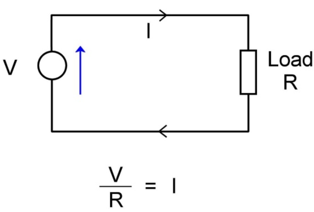
A simple circuit is depicted in this diagram.
Example:
A load with a resistance of 4 ohms is connected to a 12 volts vehicle battery. What is the current situation?
V/R = I
V is equal to 12 volts.
4 ohms = R
As a result, current I = 12/4 = 3 amps.
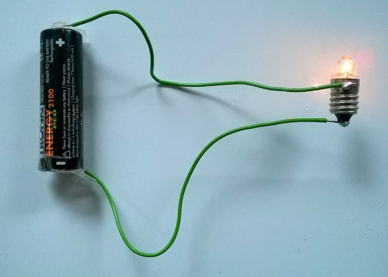
A basic circuit with an AA battery and a light bulb. The voltage source for current to flow in a loop around the circuit and through the bulb is the AA cell.
Take a look at my other article for more information on current, voltage, and resistance in AC and DC.
What Can a Multimeter Measure and Tell You?
You may use a basic multimeter to check the following:
Direct current voltage
Direct current (DC)
AC (alternating current) voltage
alternating current (AC) (not all basic meters have this function)
Resistance
Continuity is signaled by a buzzer or a tone.
Additionally, meters may include the following features:
Measuring capacitance
HFE or DC current gain transistor
Temperature monitoring with a second probe
Test with a diode
Frequency analysis
On an LCD display or scale, the value measured by the device is displayed.
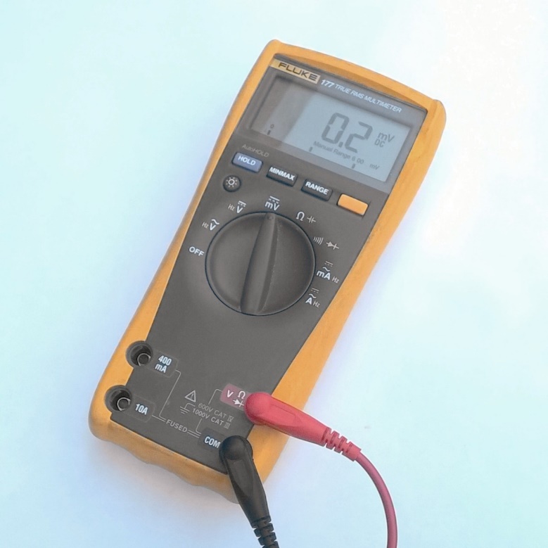
A professional Fluke model 177 multimeter with a DC volts accuracy of 0.09 percent.
Chapter two
Digital Meter Components
The display/Showcase. This is usually a 7-segment LCD panel with many digits. LED displays on some scientific devices, on the other hand, are simpler to read in certain lighting circumstances.
Range Selector Dial (Rotary). This allows you to choose the meter function that you want to use. It also selects the range on a non-auto ranging meter.
Ports for connecting. These are female sockets with a diameter of 4 mm, into which 4 mm probe leads are inserted.
Probes. On one end, there is a sharp tip for contacting against the point of measurement, and on the other end, there is a plug for insertion into a connecting socket.
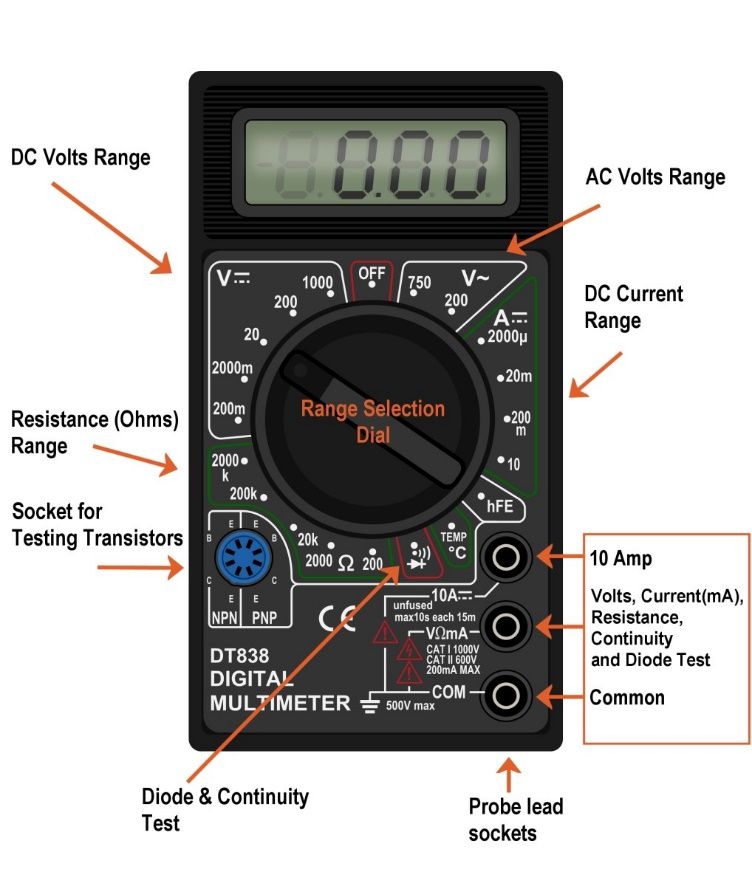
The function (volts, amps, resistance) and range are selected using a range selection dial. Take note of the symbols for AC and DC. An explanation can be found in the graphic farther down this post.
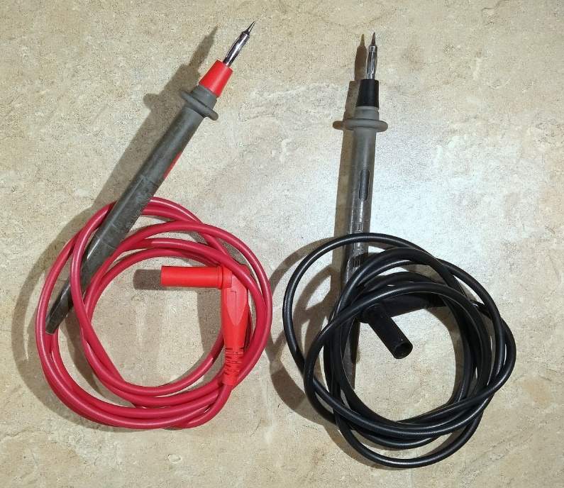
Probes for multimeters
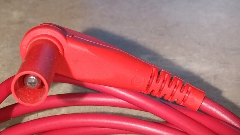
A multimeter probe with a 4mm plug on the end.
How to connect a socket on a meter .
Because the configuration is non-standard and varies by meter brand/model, it's critical to understand the purpose of each socket to avoid causing damage to the meter:
The black probe lead is inserted into the common socket (com). On all meters, this is standard.
The red probe lead is plugged into a socket labelled VmA for measuring voltage, resistance, or low current ( mA stands for "milliamps" for current measurement, and the Greek letter Omega stands for ohms, the unit of resistance).
There will be one or more different sockets for connecting the red probe led to measure current if the socket does not say "mA" as indicated above. The maximum current range will be indicated by the letters "A" or "mA" on these sockets (e.g., 10A for high current readings and 400 mA for lower current readings).
What Is the Best Way to Set Up a Multimeter to Measure Volts, Amps, and Ohms?
A rotating range selection dial is typically used to establish voltage, current, and resistance ranges. This is set to the quantity that is being measured, for example. Volts AC, Volts DC, Amps(current), and Ohms (resistance).
Each function will have many ranges if the meter is not auto ranging. The DC volts function range, for example, will offer ranges of 1000V, 200V, 20V, 2V, and 200mV. Using the smallest range feasible increases the reading's significance.
NOTE
Working with mains electricity can be risky, and if you don't take the proper measures, you could get a shock or be electrocuted.
Before using your multimeter to measure mains current or voltage, read and understand the handbook and any warnings it contains.
When connecting electrical connections, turn off the power.
Chapter three
How to Take Voltage Readings
. If there is a risk of shorting out closely spaced adjacent wires, terminals, or other locations with different voltages, turn off the circuity/wiring under test.
. Connect the black ground probe wire to the meter's COM connector (see photo below).
Connect the red positive probe led to the V socket (which may also be identified with the Greek letter "omega" and a diode symbol).
If the meter includes a manual range selection dial, use it to choose between AC and DC volts and a range that will provide the desired precision. So, if you measure 12 volts on the 20 volts range, you'll get more decimal places than if you measure it on the 200 volts range.
Turn the dial to the 'V' setting with the symbol for AC or DC if the meter is auto ranging (see "What Do the Symbols on the Range Dial Mean?" below).
To measure voltage, a multimeter must be linked in parallel in a circuit (see diagram below). As a result, the two test probes must be linked in parallel to the voltage source, load, or any other two sites where voltage must be monitored.

