INTRODUCTION
The main goal is to make a compendium of useful projects to solve practical problems. In the future I intend to add more projects; and I assume that you know electronic and Microchip C18 compilerand C++ language. These projects have been compiled with MPLAB C18, and the board that I have used is PIC18F2550. The main sensors and electronic modules that I have been used in this compendium were the following:
- US1881
- LM35DZ
- MQ-2
- MQ-7
- PIR
- FAN
- MOTOR CD
- PUMP
- LED
Each chapter has a simple explanation, electronic diagram, list of part, source code, photographs and links of a video, tutorial and download source. My Youtube channel and blogs are the following: https://www.youtube.com/channel/UCuePeN-Qvq3lvUVQavo4jiQ http://hubpages.com/@guillengap http://guillengap.blogspot.mx/ Email:
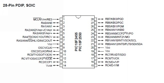
Features Full Speed USB 2.0 (12Mbit/s) interface
- 1K byte Dual Port RAM + 1K byte GP RAM
- Full Speed Transceiver
- 16 Endpoints (IN/OUT)
- Internal Pull Up resistors (D+/D-)
- 48 MHz performance (12 MIPS)
- Pin-to-pin compatible with PIC16C7X5
Program Memory Type: Flash Program Memory (KB): 32 CPU Speed (MIPS): 12 RAM Bytes: 2,048 Data EEPROM (bytes): 256 Digital Communication Peripherals: 1-UART, 1-A/E/USART, 1-SPI, 1-I2C1-MSSP(SPI/I2C) Capture/Compare/PWM Peripherals: 2 CCP Timers: 1 x 8-bit, 3 x 16-bit ADC: 10 ch, 10-bit Comparators: 2 USB (ch, speed, compliance): 1, FS Device, USB 2.0 Temperature Range (C): -40 to 85 Operating Voltage Range (V): 2 to 5.5 Pin Count: 28
BLINK A LED
Circuit Diagram
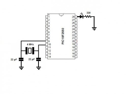
Components:
- Microcontroller PIC18F2550
- Crystal 4 MHz
- Capacitor 22 pF
Source code with the explanation in the comments and compiled with C18 code.
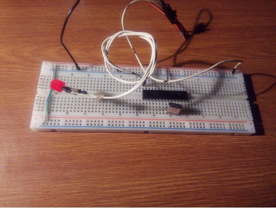
Links: Video: https://youtu.be/g8d5MTMCVq8 Source code: https://drive.google.com/file/d/0B8XMvcdJvBBYdEJ4d2dSVnAyY00/view?usp=sharing
USB FREQUENCY COUNTER AND VOLTMETER
Using PIC18F2550 for connecting analogue and digital signals to the USB port.

Links: Video: https://youtu.be/g8d5MTMCVq8 Source code: https://drive.google.com/file/d/0B8XMvcdJvBBYdEJ4d2dSVnAyY00/view?usp=sharing
USB FREQUENCY COUNTER AND VOLTMETER
Using PIC18F2550 for connecting analogue and digital signals to the USB port.
Included Visual Basic 6 and Microchip C18 code. The PIC microcontroller has 10 bit analogue to digital converter, by selecting 8 bits conversion the 2 LSB are ignored. The circuit is powered by the USB. The interface to the PC is HID class. The frequency counter has a range of up to 4MHz (24bits). Inputs samplings can be done at rates of 1 per second and 1 every 0.1 second.
HID class is a class of devices like the mouse and the keyboard; the data transfer rate is limited to 64KB/S. Circuit Diagram 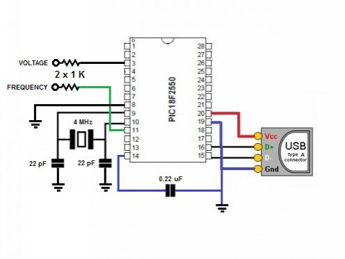 Components:
- Microcontroller PIC18F2550
- USB Type A
- Crystal 4 MHz
- Capacitor 22 pF, o.22 uF
Source code with the explanation in the comments and compiled with C18 code. #include #include #include #include "usb.h" // Note: there are timing related problems associated with GET_FEATURE // when run at less than 48 MHz //#define CLK_48MHZ 1 #pragma config PLLDIV=1, CPUDIV=OSC1_PLL2, USBDIV=2, FOSC=XTPLL_XT//, FCMEM=OFF //CPUDIV=OSC1_PLL2=48MHz, CPUDIV=OSC3_PLL4=24MHz #pragma config IESO=OFF, PWRT=OFF, BOR=ON_ACTIVE, BORV=3, VREGEN=ON, WDT=OFF #pragma config MCLRE=OFF, PBADEN=OFF, CCP2MX=OFF, STVREN=ON, LVP=OFF, XINST=OFF, DEBUG=OFF // HID feature buffer volatile unsigned char HIDFeatureBuffer[HID_FEATURE_REPORT_BYTES]; #pragma code low_vector=0x8 void low_interrupt (void) { } #pragma code // Allocate buffers in RAM for storage of bytes that have either just // come in from the SIE or are waiting to go out to the SIE. unsigned char txBuffer[HID_INPUT_REPORT_BYTES]; unsigned char rxBuffer[HID_OUTPUT_REPORT_BYTES]; unsigned int timestamp=0; extern byte transferType; unsigned char timebase, freq3; //counter's vars //prototypes void UserInit(void); void ProcessIO(void); //***************************************************************** // Entry point of the firmware void main(void) { // Set all I/O pins to digital //ADCON1 |= 0x0F; // Initialize USB UCFG = 0x14; // Enable pullup resistors; low speed=0x10, full speed mode=0x14 deviceState = DETACHED; remoteWakeup = 0x00; currentConfiguration = 0x00; // Call user initialization function UserInit(); while(1) { // Ensure USB module is available EnableUSBModule(); // As long as we aren't in test mode (UTEYE), process USB transactions. if(UCFGbits.UTEYE != 1) ProcessUSBTransactions(); // Application specific tasks ProcessIO(); } } //******************************************************************** // Entry point for user initialization void UserInit(void) { TRISCbits.TRISC0=1; //counter's input TRISBbits.TRISB4=1; TRISBbits.TRISB5=0; TRISAbits.TRISA0=1; TRISAbits.TRISA1=1; ADCON1=0B1000; //ref 5v, ch0-4 analogue ADCON2=0B101110; //Ttad, left just. ADCON0=0B101; //input on ch.1, adc ON T1CON=0B01000110; //prescale=1:1, timer=off, osc=off, input=pin11 T2CON=0B1111011; //prescale=1:16, output=1:16, timer=off PR2=233; //5mS period timebase = 0; } #define LOBYTE(x) (*((char *)&x)) #define HIBYTE(x) (*(((char *)&x)+1)) //******************************************************************** // Central processing loop.
Whenever the firmware isn't busy servicing // the USB, we will get control here to do other processing. void ProcessIO(void) { byte rxCnt; // User Application USB tasks if ((deviceState < CONFIGURED) || (UCONbits.SUSPND==1)) return; // Find out if an Output report has been received from the host. rxCnt = HIDRxReport(rxBuffer, HID_OUTPUT_REPORT_BYTES); // If no bytes in, then nothing to do if (rxCnt == 0) return; ADCON0bits.GO_DONE = 1; //start ADC //Frequency Counter TMR1L = TMR1H = freq3 = 0; //clear timers PIR1bits.TMR1IF = 0; PIR1bits.TMR2IF = 0; PORTBbits.RB5 = rxBuffer[1]; //1 sec time base LED if(rxBuffer[1]){timebase = 200;} //time base=1 sec else{timebase = 20;} T1CONbits.TMR1ON = 1; //start count T2CONbits.TMR2ON = 1; while(timebase){ while(!PIR1bits.TMR2IF){ if(PIR1bits.TMR1IF){++freq3; PIR1bits.TMR1IF = 0;} } PIR1bits.TMR2IF = 0; --timebase; } T1CONbits.TMR1ON = 0; //stop count T2CONbits.TMR2ON = 0; //Data to send to host txBuffer[0]=ADRESH; txBuffer[1]=ADRESL; txBuffer[2]=timebase; txBuffer[3]=TMR1L; txBuffer[4]=TMR1H; txBuffer[5]=freq3; // As long as the SIE is owned by the processor, we let USB tasks continue. while (ep1Bi.Stat & UOWN) ProcessUSBTransactions(); // The report will be sent in the next interrupt IN transfer. HIDTxReport(txBuffer, HID_INPUT_REPORT_BYTES); } //********************************************************************* // Initialization for a SET_FEATURE request. inPtr = (byte*)&HIDFeatureBuffer; } } // Post processing for a SET_FEATURE request. inPtr = (byte*)&HIDFeatureBuffer; } } // Post processing for a SET_FEATURE request.



 This work is authors property, and has been registered on the Website http://www.safecreative.com with the registration code 1609269275953 and protected under the License Creative Commons Attribution-NonCommercial-NoDerivatives 4.0
 Features Full Speed USB 2.0 (12Mbit/s) interface
  Components:
  Links: Video: https://youtu.be/g8d5MTMCVq8 Source code: https://drive.google.com/file/d/0B8XMvcdJvBBYdEJ4d2dSVnAyY00/view?usp=sharing
  Components: