1.1 Introduction
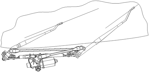
Automotive windshield wiper systems, in conjunction with washer systems, are used in vehicles to remove contaminants such as rain, sleet, snow, and dirt from the windshield. As shown in Fig. ].
Fig. 1.1
A typical wiper system consists of wipers, motor, and a linkage, and wiper arms
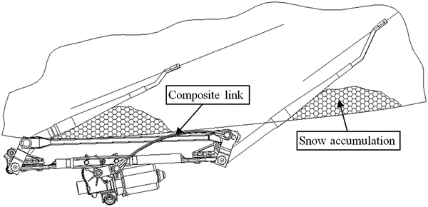
Figure shows that snow has accumulated above the cowl screen and caused the normal wiping pattern of the system to be restricted. Under such conditions, the loads in the wiper system have been observed to be approximately four times greater than those encountered under normal wiping conditions for a particular application. The elevated loads are due to two factors: (1) As the arm(s) and/or blade(s) come into contact with the restriction, the speed of the wiper system decreases and the output torque of the motor increases. (2) This factor is aggravated by the very large mechanical advantage of the wiper linkage near the reversal positions.
Fig. 1.2
Restricted wiping pattern due to snow accumulation
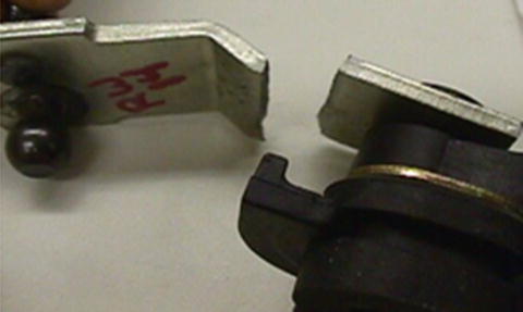
In extreme cases, the loads that result from restricting the wipe pattern can cause failures. For example, Fig. depicts a 5-mm thick hardened steel rocker arm that has fractured as a result of such a loading. Clearly, such a damage is unacceptable from both safety and warranty standpoints.
Fig. 1.3
Fractured rocker arm resulting from snow accumulation
Penrod and Dong []. This couplerreferred to as the composite linkhas the advantage of being sufficiently stiff during normal operation providing very good pattern control. However, in the event that elevated loads occur, the coupler is designed to buckle at a prescribed load level (i.e. the critical load). Once buckled, the coupler becomes extremely compliant. As a result, the peak loading of the coupler and, moreover, the entire system, can be limited and greatly reduced when compared to the same system without the composite link.
Figure shows the operating principle of the composite link. In the illustration the wiper arms have encountered snow/ice accumulation (depicted by the hatched pattern) above the cowl screen that blocks the normal wiping pattern of the system. As a result, the wiper system loads have increased sufficiently to buckle the composite link (depicted by the arcuate member of the wiper linkage). Once buckled, the composite link behaves nearly perfectly-plastic. As a result, the chord length of the composite link decreases significantly without a corresponding appreciable increase in axial load. Thus the crank is able to continue rotating and the wiper system is enabled to wiper at a reduced area above the restriction.
Fig. 1.4
Operating principle of the composite link
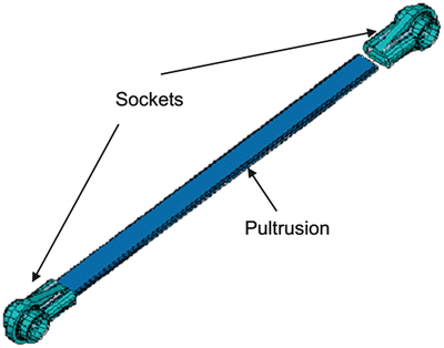
The composite link is an assembly of a 16.7 mm 5.2 mm rectangular cross-section pultrusion and glass-filled plastic sockets attached at either end, as shown in Fig. ]. Because the loads exerted on the coupler vary in magnitude and direction during each wiping cycle, the joint between the sockets and the pultrusion is critical and must be robust.
Fig. 1.5
Composite link assembly
Initially, it was planned to attach the sockets to the pultrusion rod using the same approach that sockets have been traditionally joined to steel couplers (i.e. over-molding the sockets around holes stamped into the ends of the traditional steel coupler). In the case of the composite link, holes were drilled into the ends of the pultrusion and the sockets were over-molded onto the pultrusions. Unfortunately, this joining method performed dismally as it was characterized by bearing stress failures of the pultrusion at relatively low tensile loads. In retrospect, this failure mode was no surprise. The pultrusions consist of longitudinally oriented continuous glass fibers bound together by a thermosetting polyester matrix. Drilling holes on the pultruded rod cuts the continuous fibers and weakens the composite structure. As such, the material has little strength on short-transverse planes where the bearing failure was observed to occur.
Since the paradigm for attaching sockets to steel links did not work, a Greenfield approach to attaching sockets to the pultrusions was embarked upon. This paper details the approach that was employed to generate, evaluate, and optimize an acceptable means of attaching the injection-molded plastic sockets to the pultrusions.
1.2 Designed Experiment for Joining Socket to Pultrusion
How can the plastic sockets be attached to the pultruded composite rod? The traditional approach of over-molding the sockets to steel links proved inadequate as was discussed previously. In order to answer this question, a set of design specifications were generated to assess design concepts against. Qualitatively, the specifications of paramount importance were that the attachment method.

