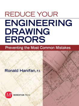
Hanifan - Reduce your engineering drawing errors preventing the most common mistakes
Here you can read online Hanifan - Reduce your engineering drawing errors preventing the most common mistakes full text of the book (entire story) in english for free. Download pdf and epub, get meaning, cover and reviews about this ebook. City: New York, year: 2010, publisher: Momentum Press, genre: Romance novel. Description of the work, (preface) as well as reviews are available. Best literature library LitArk.com created for fans of good reading and offers a wide selection of genres:
Romance novel
Science fiction
Adventure
Detective
Science
History
Home and family
Prose
Art
Politics
Computer
Non-fiction
Religion
Business
Children
Humor
Choose a favorite category and find really read worthwhile books. Enjoy immersion in the world of imagination, feel the emotions of the characters or learn something new for yourself, make an fascinating discovery.
- Book:Reduce your engineering drawing errors preventing the most common mistakes
- Author:
- Publisher:Momentum Press
- Genre:
- Year:2010
- City:New York
- Rating:5 / 5
- Favourites:Add to favourites
- Your mark:
- 100
- 1
- 2
- 3
- 4
- 5
Reduce your engineering drawing errors preventing the most common mistakes: summary, description and annotation
We offer to read an annotation, description, summary or preface (depends on what the author of the book "Reduce your engineering drawing errors preventing the most common mistakes" wrote himself). If you haven't found the necessary information about the book — write in the comments, we will try to find it.
Hanifan: author's other books
Who wrote Reduce your engineering drawing errors preventing the most common mistakes? Find out the surname, the name of the author of the book and a list of all author's works by series.
Reduce your engineering drawing errors preventing the most common mistakes — read online for free the complete book (whole text) full work
Below is the text of the book, divided by pages. System saving the place of the last page read, allows you to conveniently read the book "Reduce your engineering drawing errors preventing the most common mistakes" online for free, without having to search again every time where you left off. Put a bookmark, and you can go to the page where you finished reading at any time.
Font size:
Interval:
Bookmark:
Reduce Your Engineering Drawing Errors: Preventing the Most Common Mistakes
Copyright Momentum Press, LLC, 2010
All rights reserved. No part of this publication may be reproduced, stored in a retrieval system, or transmitted in any form or by any means-electronic, mechanical, photocopy, recording or any other except for brief quotations, not to exceed 400 words, without the prior permission of the publisher
First published in 2010 by
Momentum Press, LLC
222 East 46th Street, New York, N.Y. 10017
www.momentumpress.net
ISBN-13: 978-1-60650-210-5 (softcover)
ISBN-10: 1-60650-210-7 (softcover)
ISBN-13: 978-1-60650-211-2 (e-book)
ISBN-10: 1-60650-211-5 (e-book)
DOI forthcoming
Cover Design by Jonathan Pennell
Interior Design by J. K. Eckert & Co., Inc.
First Edition January 2010
10 9 8 7 6 5 4 3 2 1
Printed in Taiwan ROC.
In this book, I will discuss only the most common errors that appear on engineering drawings and the basic usage and understanding of the most frequently used drawings.
All drawings will contain errors, but if you can eliminate many of those errors before the engineering design checker or your supervisor reviews your drawing, it will go through much easier. Your reputation is at stake! Your supervisor and the engineering design checker will see everyones work and know their errors. They know your weak areas and who produces good work and who doesnt. It is helpful to know what they look foror should be looking for.
Herein we discuss the most common errors on drawings and the most frequently used drawing types. The data contained on these drawings, when not done properly, is subject to interpretation instead of universally published rules. Geometric dimensioning and tolerancing has become very complex, but it need not be. The best policy is to keep it simple but stringent enough to build good parts. As the drawing becomes more complex, the probability of misinterpretation increases. Also, it can increase the cost of the product and inspection tooling. Engineering is a field where rules are structured and uniform to allow for global repeatability in interpretation. These rules are the foundation of our profession and should never be violated, regardless how minor. The impact created from these violations may range from minor to major, immediate or future. Procurement, manufacture, inspection, stocking, and assembly and sparing of parts or equipment may be impaired. There normally is no real reason to deviate from established and approved rules.
DESIGN IS COMPLETE
You have labored many hours developing your design, and now you are finally done. Whichever computer aided design (CAD) system you used, it has been a proven to be a tremendous asset, and you are very proud of your accomplishment. However, now it is time to prepare drawings so that parts can be fabricated, inspected, subcontracted, assembled, tested, or procured. The initial design is a very important part of your effort, but now it is time for the real world and the documentation of your product. This is the most important step in your design. This is what everyone will see, and it is what people will use to evaluate you and your accomplishments. The drawing is the one item that is visible to everyone. The primary focus is to document your design on drawings with such accuracy that no bad parts will be made and to ensure that there is no ambiguous information. The reality is that every drawing will contain errors; some will be serious and some minor. Even seemingly minor mistakes can cost millions of dollars. Regardless of the type of error, someone will be impacted.
From your drawing, procurement will order materials/parts or will subcontract parts to be made, production will set in motion the assembly steps, parts will be made, inspection plans will be developed, and drawings will be sent out to prospective manufacturers. All drawings will contain mistakes, but with careful attention, the severity of these mistakes can be minimized. Everyone will scrutinize your drawing, and your reputation, your department, and the company are at risk.
What you designed, as shown in your CAD system, is designed at nominal (average), and everything fits. It is perfect! But in reality, when parts are fabricated, they will contain many errors because of tool wear, operator errors, or misinterpretations. The drawing that you have prepared defines how much error is acceptable.
The data on your tube normally goes nowhere; it is the paper (drawing) that will now receive everyones attention. Manufacturing, procurement, and inspection will be the main users of the data that you have developed. Drawings will be sent out for quotes to fabricate or buy, and parts will be inspected, manufactured, and assembled from the information contained on these drawings. There are instances in which a model is sent to subcontractors in lieu of a drawing; however, this very seldom works.
The information on the drawing is to be presented in such a manner that there can be no misinterpretation of the intent of the end item. All features and information require complete inspection criteria (acceptance/rejection). This sounds easy; however, it isnt. Each and every part of your design has to be documented in some manner. It may consist of new drawings or usage of existing drawings, commercial specifications, vendor parts, and so on. Materials and finishes need to be specified, configuration completely defined, and any other necessary characteristics such as installation of inserts, burr removal, flash specified, parting lines, surface texture, and so forth all need to be specified.
Requirements vary, depending on the type of item being depicted. It is very important to keep in mind the intended uses of the drawing. It may have to meet requirements imposed by a contract or your own companys standards. The drawing also becomes a legal and binding contract between your company and other users. Primarily, your drawing will be used by a manufacturer, but it is not a manufacturing drawing. It is an end-item drawing, defining only end-item requirements and not the methods of accomplishing the action. Hence, only a hole size is given, and not the method of manufacture, unless the actual method of manufacture is critical. Remembera method is very difficult to inspect, and the method, when specified, does become an item requiring inspection.
You have dimensioned your parts completely, and, if done properly, inspection will have no problem understanding your intent. In all probability, you used geometric dimensioning and tolerancing (GD&T) to define your product. GD&T is a very complex endeavor, and you must understand exactly what you have placed on your drawing. Understanding of your tolerance zone, the shape and extent of it, and how the size of it may increase/decrease is of the utmost importance. The more exotic your GD&T application is, the greater the difficulty in the interpretation. If you dont understand completely the tolerance zone, then you cant expect others to understand. If the application is not contained in ANSI/ASME Y14.5, then you cannot use it. ANSI/ASME Y14.5 contains the only approved rules, and any other documents contain only someone elses interpretations. The best rule of thumb is to keep it simple but stringent enough to build good parts. Remember, the tolerances increase the difficulty of fabrication and inspection, which impacts the cost.
It is very important to pick the right type of drawing for the intended function. There are detail (part) drawings, assembly drawings, testing specifications, many different types of procurement drawings, drawings for altering existing parts, reference drawings (such as piping documents), schematics, interconnect diagrams, installation drawings, and others. Assembly drawings will contain a Parts List or Bill of Material (separate or integral). The most common of these drawings, and their requirements, will be discussed in Chapter 4. These drawings and their requirements are controlled by ASME Y14.24 and ASME Y14.100. ASME Y14.24 specifies the types of drawings allowed and their requirements, whereas ASME Y.14.100 specifies approved engineering drawing practices.
Next pageFont size:
Interval:
Bookmark:
Similar books «Reduce your engineering drawing errors preventing the most common mistakes»
Look at similar books to Reduce your engineering drawing errors preventing the most common mistakes. We have selected literature similar in name and meaning in the hope of providing readers with more options to find new, interesting, not yet read works.
Discussion, reviews of the book Reduce your engineering drawing errors preventing the most common mistakes and just readers' own opinions. Leave your comments, write what you think about the work, its meaning or the main characters. Specify what exactly you liked and what you didn't like, and why you think so.


