1. 50 Years in Carbon Fibre, 60 Years in Composites
I am sure someone must have said this before, but in my experience there is nothing like a well-designed experiment to ruin a perfectly good theory.
1.1 A Perspective: 19562016
Early postwar cars were, to say the least, not well made. After less than 10 years, there were serious problems with paint defects and corrosion. Most private owners could not afford to take the car to a garage so they chose to do their own repairs. Paintwork was relatively easy to deal with, but where the steel was corroded completely through, the only solution was welding and an expensive garage repair. But then, in the mid-1950s, car accessory firms began to market glass fibre repair kits, using woven or random glass fibre mat and a polyester resin. Thus, it was that even schoolchildren could repair a car with GRP. The resin had a catalyst and a hardener that had to get mixed accurately and thoroughly and then applied briskly before the resin began to gel. First, the surfaces had to be cleaned and dried to bare metal, any moisture providing a sure recipe for disaster. On the other hand, any form of hand-applied rust-preventing chemicals onto the bare metal was faith in untried chemistry and usually led to failure of the bond quite quickly. The second lesson was to mix the polyester ingredients quickly and accurately. Third, the glass fibre mat had to be impregnated thoroughly before the mixture began to gel. Then, after the GRP had hardened, it could be smoothed with a grinder and wet and dry emery paper prior to painting. And here was the fourth lesson; the system was suitable for painting when a film of water covered the surface. This, of course, we know now as the water break test.
In 1961, the Royal Aircraft Establishment at Farnborough, UK, was interested in using filament wound glass fibre composites for rocket motors. At that time, and under the supervision of Dr W. G. Wood in the Department of Mechanical Engineering at the Imperial College, Adams [] refer to Tsai, Thielmann, and Adams to give the correct time trace.
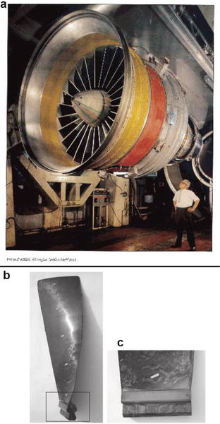
In the early 1960s, Watt, Philipps, Johnson and colleagues at RAE Farnborough found that by heating and stretching polyacrylonitrile (PAN) fibres, they could make high modulus (200500 GPa) and high-strength (12 Gpa) carbon fibres. While glass fibres were strong, Their Youngs modulus was only 70 GPa. These new carbon fibres opened new and amazing opportunities. There was a lot of excitement in the industry and academia about these new fibres. Farnborough, Rolls-Royce, Courtaulds and Morgan Crucible all made their own version of carbon fibres. Fibres were given to academics, research establishments and industry to advance the science and engineering of carbon fibre composites. Rolls-Royce produced the fan blades shown in Fig. for their new RB 211 three-shaft gas turbine. Philipps and Watt were very generous to the academia. They not only made their new fibres available but also gave advice on how they could be impregnated with epoxy or polyester resin to make carbon fibre-reinforced composites.
Fig. 1.1
( a ) RB 211 engine showing the fan blades, ( b and c ) blade and detail of the root fixing [( b and c ) Courtesy of the Farnborough Air Sciences Trust Museum]
Unidirectional CFRP specimens were made using a Bakelite 17749 polyester resin system mixed 100:2:2 with a catalyst and an accelerator using Lesley Philipps leaky mould technique. This Bakelite system had a slow reacting chemistry to give time for laminators to do what they had to. The specimens were 215 mm long, 12.7 mm wide and 12.7 mm, for torsion, or 2.54 mm, for flexure, thick (the astute will have noticed the obvious conversion from inches to mm). In effect, alternate layers of resin and fibre were laid in the mould, taking care not to introduce much air and sucking out any obvious bubbles with a hypodermic syringe. In order to achieve about 50% volume fraction, the quantities had to be precisely determined. A plunger was then carefully lowered onto the resin/fibre mixture, and force was used to compress it until resin leaked out at the sides. The resin was allowed to gel at room temperature (34 h) and the specimen was then cured, under pressure, at 100 C for 45 h. Plates were made 250 mm square and 2.5 mm thick. Care had to be taken that the fibres stayed where they were wanted and were not displaced by movement of the resin towards the edges. Flat plates could be observed visually, but Rolls-Royce had more of a problem with their thick and twisted RB 211 fan blades. To overcome this, their sheets of dry carbon fibre were stitched about every 10 cm. Because carbon fibres are almost transparent to X-rays, Rolls-Royce incorporated glass fibres (which are not X-ray transparent) so that they could monitor fibre alignment in the cured blades. Figure shows a CFRP blade and blades assembled in the RB 211 engine; the man standing in the picture gives the scale of the blades and engine.
The best methods of manufacturing composites as specimens for research as well as industrial applications (as led by Rolls-Royce) were being actively pursued. Gelation could be observed by touching the leaked-out resin with a matchstick. This was important because if the mould was closed when the resin was liquid, the fibres would be displaced. If the mould was closed when the resin had reached a late stage of gelation, it was impossible to squeeze out the air bubbles, so the plate would contain a lot of voids. Visual inspection showed that some specimens were good, some bad. Sometimes, the fibres were not straight, sometimes there was resin starvation. The learning curve was still steep. With glass fibres, bubbles of air could be seen; carbon specimens must also have contained bubbles, but these could not be seen. So how could the quality of the CFRP be assessed? The main objective at this stage was to make specimens for measuring damping and the elastic modulus. This required straight fibres (unidirectional material was used at this stage) with no voids and a controlled volume fraction. It was noted that visually poor specimens had a lower E modulus and higher damping than good specimens. But as only good material was wanted, most of the defective material was discarded.
In about 1970, there was an important breakthrough. Sheets of fibre could now be obtained which were pre-impregnated with resin which was just sufficiently cured so as to remain holding the fibres in place between paper sheets which had been coated with a release agent. It was now possible to make laminated plates with fibres in any direction. Initially, there was an excess of resin which had to be squeezed out as in the original leaky mould technique, but soon the resin/fibre proportions were carefully controlled so that plates could be made without any squeeze out.
Of course, there had to be care in the symmetry of the laid-up laminae, or the cured sheet would twist or bend (or both) when released from the mould. This is because of the low coefficient of thermal expansion (CTE) in the fibre direction but a far from zero CTE in the transverse direction. When the resin is liquid or soft, there is a stress-free condition. If cure takes place at room temperature, only resin cure shrinkage can cause any residual stresses. But since most cure cycles involve cure in excess of 100 C and often approaching 200 C, significant stresses will be built in to the laminate when it is cooled. A suitably symmetric laminate will not twist or bend, but the stresses between the laminae are there nonetheless. These interply laminate stresses are always present in composites as the highly cross-linked cured resins will have little or no creep. Thermal cycling, such as will occur with an aircraft, will induce fatigue stresses between the plies. The laws of physics do not change .

