1Energy Systems, School of Electrical Engineering and Telecommunications, The University of New South Wales Sydney, Australia
1.1 The role of motor drives in modern industry and energy usage
Electric drives occupy a central role in many industrial processes and equipment. These continue to become ubiquitous every day, as more and more applications become highly automated, controlled precisely and efficient. There are many processes that benefit form continuously controllable drives. Material processing, handling, transportation, mining, rolling mills, machining centres and guidance systems are a few of the examples in which continuously variable speed is virtually indispensable nowadays. These processes also strive for higher control accuracy in order to deliver products the specifications of which are much tighter than before. The control accuracy must also overcome disturbances arising from supply conditions to the drive converter and load conditions applying on the drive shaft. Recently, electric drives are intruding into the main traction/motive element of vehicles, which for a long time has remained as the bastion of internal combustion engines. This may lead, potentially, to a huge expansion of application of electric drive systems. The use of drive systems for wind power conversion equipment is another application which is also opening up a new and large application area for electric drive systems.
It can be stated with confidence that the age of fixed speed motor drives is coming to an end in not too distant future. Continuously variable-speed drive systems allow the inflexible motor torque-speed characteristics of fixed speed drives to readily match with the characteristics of load. This is an attribute that is unmatched and unsurpassed by any other variable speed systems. The use of inverter-driven variable speed drives in air-conditioning systems, in household, offices, factories, pumping installations and in aircrafts has led to huge savings of energy. Many more applications are poised to benefit in terms of efficiency from the use of electric drives ranging in power from a few watts to a few megawatts, in speeds from a few revs/min to 100s of krevs/min. The vast application areas mentioned above require many different types of motors, associated appropriate power converters and controller designs. This book is an attempt to encompass the description of some of elements in electric drive systems.
The elements of an electric drive system are drawn from a number of disciplines as indicated in . At the heart of an electric drive is the electric motor (AC, DC, switched reluctance and so on), the understanding and design of which stem from electromagnetic and machine theory. Design for certain steady-state performance in terms of cogging and developed torque, speed range and efficiency, and for meeting the requirements of an application are addressed increasingly through elaborate and very sophisticated design tools based on finite element analysis techniques. The dynamic performance of the machine and operating speed are addressed to some extent in this process; however, power electronic converters and control theory (real-time discrete control) have a large role to play in this. The representation of the load requires some basic understanding of mechanics for applications with fixed mass or moment of inertia. However, for more complex applications in robotics, multimachine drives with rotation in more than one axes requires deeper understanding of mechanics and mechanical system modelling.
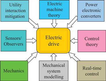
Figure 1.1 Elements of an electric drive system
The accuracy and bandwidth of sensors for sensing the applied voltages and currents to the motor, and the speed and position of the motor shaft also have important influence on the dynamics of the drive system. Isolated voltage and current sensors using the Hall and, recently, magneto resistive effects have delivered high voltage and current-sensing capabilities with galvanic isolation and high bandwidth. In some applications, speed and position sensors are a burden and a weak link in a drive system, not to mention their costs and requirement of secure and reliable housing. While voltage and current sensors can be located inside the converter cubicle, which is sometimes at a distance from the motor, cables from shaft sensors to the cubicle that houses the converter and controllers may be a serious issue for some applications. Often certain signals cannot be sensed, such as the air gap or rotor flux linkage and machine resistance. Elaborate model-based observers are used for obtaining these signals. Elimination of shaft position and speed sensors entirely and obtaining these signals using a variety of techniques which use analyses of the sensed voltages and currents to the motor are being aggressively developed.
Converter-driven drive systems which are connected to the AC grid for their power supply or inject power into the AC grid tend to inject harmonics into the grid, which in turn affects the performance of the motor drive. The topology and control of converter systems can mitigate this utility interaction to a large extent, at the cost its increased complexity of the converters and their controls. are simultaneously coordinated and driven with references that specify the motions of each drive. The accuracy and dynamics which the drives achieve determine the quality of the machined product and the productivity of the process.
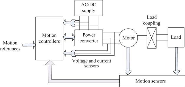
Figure 1.2 Typical structure of a variable-speed-drive system
1.2 Controller hierarchy for electric drives
From the fundamental laws of motion, the traditional structure of controller arrangements follows the hierarchical structure indicated in . The acceleration (torque), speed and position controllers are embedded within progressively faster and decoupled control loops, whereby the controllers of each section can be designed and tuned to address the local indices and limitations of current (torque), speed and position without consideration of the other controllers. The innermost controller is for torque, the reference for which is the output of the speed controller. The reference for the speed controller is the output from the position controller, if any. The speed reference also specifies the rotor/air-gap flux; it is normally at the rated level for all speed below base speed and reduced (field weakening) for speed that are higher than base speed. The control bandwidth of each stage is six to ten times faster than the preceding stage, leading to decoupled control. This practice is advantageous to application engineers who install and maintain the drive in an application.
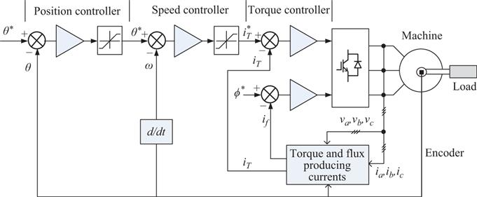
Figure 1.3 The hierarchical controller scheme from Newtons laws of motion
depicts the drive structure for DC motor drives with pulse-width modulated converters for the armature and field circuits. For motor drives up to a few kW, permanent magnets may be used for filed excitation, leading to considerable reduction of motor size and additional windings that allows better decoupling of the torque producing (armature) currents and the rotor field, resulting also in improved operational features. In this case, Converter 2 is not required, and the drive speed is limited to base speed that occurs for the rated armature voltage applied. Most DC servo motors have this structure. For larger power capacity DC drives, thyristor converters are used for both armature and field circuits. A mains-frequency (50 or 60 Hz) input transformer is often required to match the motor rated voltage with the utility AC input voltage for operation of such drives. In order to address the utility interaction, the ACDC converter, which makes available the DC voltage source to the pulse width modulation (PWM) converter 1, is normally a PWM rectifier allowing unity power factor rectified DC supply for the PWM drive. This calls for an additional converter, unlike the case for naturally commutated thyristor converter-driven DC motor drive. Mitigation of utility interaction for thyristor converter-driven DC motor drive in larger capacity is often addressed through the use of multiphase converters with pulse number higher than 6.

