PLC PROGRAMMING
USING SIMATICMANAGER
FOR BEGINNERS
WITH BASIC CONCEPTS OFLADDER LOGIC PROGRAMMING
PLC PROGRAMMING USINGSIMATIC MANAGER FOR BEGINNERS: WITH BASIC CONCEPTS OF LADDER LOGICPROGRAMMING
PARTH PATEL
Published by PARTH PATEL at Smashwords
Copyright 2020 PARTHPATEL
Discover other titlesby PARTH PATEL:
MANAGE YOURMIND: 20 SIMPLE STRATEGIES TO BEAT DEPRESSIONAND ANXIETY
Smashwords Edition,License Notes
This eBook is licensedfor your personal knowledge only. This eBook may not be re-sold orgiven away to other people. If you would like to share this bookwith another person, please purchase an additional copy for eachrecipient. If youre reading this book and did not purchase it, orit was not purchased for your use only, then please return to yourfavourite eBook retailer and purchase your own copy. If you enjoyedthis book, please encourage your friends to download their own copyfrom their favourite authorized retailer. Thank you for respectingthe hard work of this author.
PREFACE
Author feelsvery happy to present this book in front of all readers who areinterested in PLC programming especially beginners. This book aimsto provide the basic knowledge of PLC programming especially usingSIEMENS S7-300/400 family PLCs to the reader. The author isprofessional PLC programmer. Present book contains all the basicsteps from project creation according to available hardware toprogram downloading in PLC. All the steps and their sequence isaccording to actual practice which is generally followed byprofessionals. All the information is to the point and written insuch a way that book can be used as handbook for beginner. A readerwill be able to create a project easily according to hardwareprovided them after reading this book. Best output will be achievedfrom this book if practical setup is available and steps arepracticed parallelly while reading. The outcome of this book willbe different for every reader depending on their creativity andinterest. The reader should clearly understand that actualapplication requirement may be different. This book will provideguideline to them using which unlimited projects can be createdwhich will be different from each other.
Basicknowledge of PLC, their importance in industry and advantages ofPLC over microcontrollers are explain in first section named asIntroduction. Explanation of universal PLC hardware is given insecond section. So that reader will be able to understand theinteraction of PLC with other industrial devices. They will be ableto decide the best hardware configuration for their application.Third section is main part of book which contains thoroughinformation about initial setup, project creation, hardwareconfiguration creation, logic creation and project downloading.Simulation of program is explained in forth section which will helpprogrammers to test & troubleshoot their programs withoutdownloading the same into actual physical PLC set. Last sectioncontains the basic knowledge and explanation of ladder logicprogramming.
INDEX
1.INTRODUCTION:
PLC is a short form ofProgrammable Logic Controller which is widely used in industry forautomation purpose. PLC is like small computer which controlsautomatic industrial machinery. Main difference between PLC andcomputer is that PLCs are specially designed for control purposewhile computers are designed for data pocessing. Microcontrollersare also used in industry but advantage of PLC is that they work onhigher voltage and current level so those signals can betransmitted to comparatively long distance without distortion forcontrol purpose. Special electrical signals like 4-20 mA, 0-10 Vcan be directly feed into PLC. PLC supports different communicationprotocols which are available ready to use. Special circuitry isrequired to be designed for same purpose in microcontrollers. Alsodata processing capacity and speed is more in PLC thanmicrocontroller.
PLCs made bydifferent manufacturers are available in market now a days. Alsodifferent models of PLC are available from same manufacturer.Application Designer can select appropriate model according toapplication requirement. Programming of SIEMENS made PLC withfamily name S7-300 and S7-400 using a software called SIMATICMANAGER is explained in this book. A programming language calledLadder Logic which is used for programming of S7-300 & 400family PLCs is also explained in last chapter.
2.HARDWARE OF PLC:
There are two parts ofPLC hardware. One is CPU and other is modules. They are called PLCset together.
CPU is mainpart of PLC set. We can call it PLC too. CPU contains the logicalprogram which is created and downloaded by a programmer and isexecuted for the control purpose of a machinery. All the softprocesses of PLC set are performed in CPU. It also contains thecommunication circuitry which performs the function of datatransmission/reception with other automation devices like HMI, IPCand other PLCs etc.
Modulesprovides interface to the CPU for input/output of electricalsignals. There are four types of modules which are digital input(DI) module, digital output (DI) module, analog input (AI) moduleand analog output (AO) module. Mixed modules are also available.Detailed description of any module can be found in their data sheetpublished by their manufacturer.
DI moduleaccepts the digital input signal of 24 V DC. 24 V represents the 1(TRUE) and 0 V represents 0 (FALSE) condition. DO module generatesthe digital output signal of DC 24 V. Each module has differentnumber of channels according to their type. If a module has 8channels then total 8 different digital inputs/outputs can be feedinto/taken out of PLC set using single DI/DO module.
Analog modulesfunctions differently according to their type. AI module acceptsthe analog input signal of 4-20 mA, 0-20 mA or 0-10 Volts. Analogsignal is converted into digital form (represented by counts) usingAI module and it is feed to CPU for further logical process. Countshave range from 0 to 27000 generally. Maximum counts may vary indifferent PLC. 0 count represents 4 mA/0 mA/ 0 Volts and 27000counts represents 20 mA/ 10 Volts. Value of any analog signalbetween maximum and minimum value can be calculated accordingly. AOmodule generates the analog output signal of 4-20 mA, 0-20 mA or0-10 Volts according to the type of module. Each module may havedifferent number of channels depending on their type.
Designershould refer datasheet of CPU and module before selecting them toensure the wiring and compatibility of PLC set with system.
3.PROJECT CREATION & PROGRAM DOWNLOADING
1. INITIAL SETUP:
Some settings in your PCare required to be changed in order to detect the PLC by itsprogramming software. These are general settings which areapplicable for almost all PLCs supporting Ethernet protocol.
Go to ControlPanel >> Network and Internet >> Networkconnections.
Right click onappropriate Ethernet connection which is used by your PLC. Click onProperties and select Internet Protocol Version 4 (TCP/IPv4). Clickon Properties.
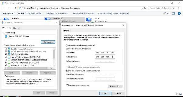
Click on UseFollowing IP address. Enter the IP address which must be in thesame range with that of PLC. I.e. if your PLC IP address is192.168.0.38 then you must set the IP address of laptop like192.168.0. ---. Set the subnet mask 255.255.255.0. This range IPaddress (192.168.0. ---) is generally preferred byprofessionals.
Note that IPaddresses of your PC and PLC must be unique. I.e. it must not matchwith the IP address of any device connected in your existingEthernet Network. Also IP addresses of both devices (PLC and PC)must be different. If you are not sure then isolate the PLC fromsystem. After that connect the same with PC before performing anyoperation.
Next page
