• Complain

Ahmet Bindal - Electronics for Embedded Systems

Here you can read online Ahmet Bindal - Electronics for Embedded Systems full text of the book (entire story) in english for free. Download pdf and epub, get meaning, cover and reviews about this ebook. year: 0, publisher: Springer International Publishing, Cham, genre: Home and family. Description of the work, (preface) as well as reviews are available. Best literature library LitArk.com created for fans of good reading and offers a wide selection of genres:

Romance novel Science fiction Adventure Detective Science History Home and family Prose Art Politics Computer Non-fiction Religion Business Children Humor

Choose a favorite category and find really read worthwhile books. Enjoy immersion in the world of imagination, feel the emotions of the characters or learn something new for yourself, make an fascinating discovery.

Ahmet Bindal Electronics for Embedded Systems
  • Book:
    Electronics for Embedded Systems
  • Author:
  • Publisher:
    Springer International Publishing, Cham
  • Genre:
  • Year:
    0
  • Rating:
    3 / 5
  • Favourites:
    Add to favourites
  • Your mark:
    • 60
    • 1
    • 2
    • 3
    • 4
    • 5

Electronics for Embedded Systems: summary, description and annotation

We offer to read an annotation, description, summary or preface (depends on what the author of the book "Electronics for Embedded Systems" wrote himself). If you haven't found the necessary information about the book — write in the comments, we will try to find it.

Ahmet Bindal: author's other books


Who wrote Electronics for Embedded Systems? Find out the surname, the name of the author of the book and a list of all author's works by series.

Electronics for Embedded Systems — read online for free the complete book (whole text) full work

Below is the text of the book, divided by pages. System saving the place of the last page read, allows you to conveniently read the book "Electronics for Embedded Systems" online for free, without having to search again every time where you left off. Put a bookmark, and you can go to the page where you finished reading at any time.

Light

Font size:

Reset

Interval:

Bookmark:

Make
Springer International Publishing Switzerland 2017
Ahmet Bindal Electronics for Embedded Systems 10.1007/978-3-319-39439-8_1
1. Fundamentals of Passive Circuit Analysis
Ahmet Bindal 1
(1)
Computer Engineering Department, San Jose State University, San Jose, California, USA
Ahmet Bindal
Email:
1.1 Laplace Transform
Laplace transform transforms a function, f(t), in time-domain to a function, F(s), in frequency domain . We will use Laplace transform to determine the impedance of a passive element in this section.
It is defined as:
11 12 Definitions of Passive Elements Current-voltage relationship - photo 1
(1.1)
1.2 Definitions of Passive Elements
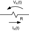
Current-voltage relationship across a resistor , R, is defined as shown in Fig..
Electronics for Embedded Systems - image 2
Fig. 1.1
Current-voltage relationship across a resistor, R
This relationship is called Ohms law and mathematically expressed as follows:
Electronics for Embedded Systems - image 3
(1.2)
Taking Laplace transform of both sides of Eq. yields:
Electronics for Embedded Systems - image 4
Thus, the impedance of the resistor becomes:
Electronics for Embedded Systems - image 5
(1.3)
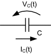
Current-voltage relationship across a capacitor , C, is defined as shown in Fig..
Electronics for Embedded Systems - image 6
Fig. 1.2
Current-voltage relationship across a capacitor , C
This relationship originates from the Coulombs law and mathematically expressed as follows:
Electronics for Embedded Systems - image 7
(1.4)
Taking Laplace transform of both sides of Eq. yields:
Electronics for Embedded Systems - image 8
where VC(0) is assumed 0 V.
Thus, the impedance of the capacitor becomes:
Electronics for Embedded Systems - image 9
(1.5)
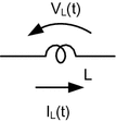
Current-voltage relationship across an inductor , L, is defined as shown in Fig..
Electronics for Embedded Systems - image 10
Fig. 1.3
Current-voltage relationship across an inductor , L
This relationship is mathematically expressed as follows:
Electronics for Embedded Systems - image 11
(1.6)
Taking Laplace transform of both sides of Eq. yields:
Electronics for Embedded Systems - image 12
where IL(0) is assumed 0 A.
Thus, the impedance of the capacitor becomes:
Electronics for Embedded Systems - image 13
(1.7)
1.3 Time-Domain Analysis of First Order Passive Circuits
1.3.1 RC Circuits
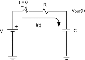
In this section, we will examine the circuit behavior of simple RC circuits. A circuit composed of a series combination of a resistor and a capacitor is shown in Fig.. The switch is assumed to close at t = 0.
Electronics for Embedded Systems - image 14
Fig. 1.4
A simple RC circuit where the switch closes at t = 0
Applying Kirchoffs voltage law to the circuit yields:
Electronics for Embedded Systems - image 15
(1.8)
But,
Electronics for Embedded Systems - image 16
(1.9)
In order to use Eq..
Electronics for Embedded Systems - image 17
(1.10)
Substituting Eq. yields:
Electronics for Embedded Systems - image 18
(1.11)
Electronics for Embedded Systems - image 19
(1.12)
In Eq. , the right side is equal to zero because V is a constant voltage and its derivative becomes zero.
We know I(t) is composed of a general and a particular solution for this first-order constant coefficient differential equation . Thus,
Electronics for Embedded Systems - image 20
But, IPART(t) = 0 since the right hand side of the differential equation in Eq. is zero .
IGEN(t), on the other hand, is expressed as follows:
Electronics for Embedded Systems - image 21
(1.13)
Thus,
114 To find s we need to take the Laplace transform of both sides of the - photo 22
(1.14)
To find s, we need to take the Laplace transform of both sides of the differential equation in Eq..
Thus,
Electronics for Embedded Systems - image 23
(1.15)
Since I(s) 0, then Eq. reveals Electronics for Embedded Systems - image 24 (characteristic equation).
Therefore, Electronics for Embedded Systems - image 25 , and I(t) becomes:
Electronics for Embedded Systems - image 26
(1.16)
To find A, we need to use the initial voltage across the capacitor . In this case, we assume VOUT(0) = 0.
But, at t = 0, we have:
Electronics for Embedded Systems - image 27
(1.17)
Thus,
Electronics for Embedded Systems - image 28
Next page
Light

Font size:

Reset

Interval:

Bookmark:

Make

Similar books «Electronics for Embedded Systems»

Look at similar books to Electronics for Embedded Systems. We have selected literature similar in name and meaning in the hope of providing readers with more options to find new, interesting, not yet read works.


Reviews about «Electronics for Embedded Systems»

Discussion, reviews of the book Electronics for Embedded Systems and just readers' own opinions. Leave your comments, write what you think about the work, its meaning or the main characters. Specify what exactly you liked and what you didn't like, and why you think so.