Osprey Modelling 38
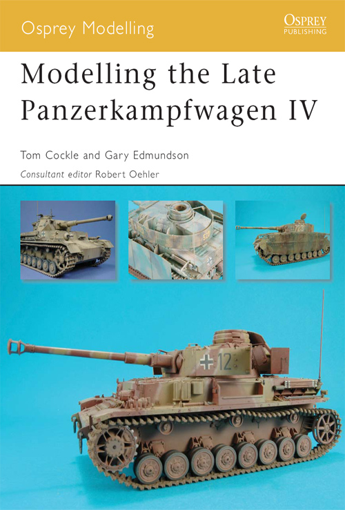
Modelling the Late Panzerkampfwagen IV
Tom Cockle and Gary Edmundson
Consultant editor Robert Oehler Series editors Marcus Cowper and Nikolai Bogdanovic
Contents
Introduction
The Panzerkampfwagen IV went through several improvements during its lifetime and is the only German tank to have been produced continuously throughout World War II.
During the battle of France in 1940, the 7.5cm KwK L/24 gun had proved itself capable of penetrating the armour of most French and British tanks. However, encounters with the heavy Russian KV and T-34 tanks in 1941 resulted in a recommendation that the 7.5cm KwK 40 L/43 be installed in the Panzerkampfwagen IV. Initially, the new tank was known as the Pz.Kpfw. IV Ausf. F2. In June 1942, the designation was changed to Pz.Kpfw. IV Ausf. G, and in July it was ordered that all Pz.Kpfw. IV fitted with the 7.5cm KwK 40 were to be known as Pz.Kpfw. IV Ausf. G.
Major production modifications included adding 30mm armour plates to the front of the hull and superstructure, replacing the Notek light with a Bosch headlight on each fender, adding smoke discharger tubes on each side of the turret, introducing a modified commanders cupola with a single hatch, adding armour skirts to the turret and hull sides, and an air filter to the right fender. A total of 1,930 vehicles were produced from March 1942 until June 1943.
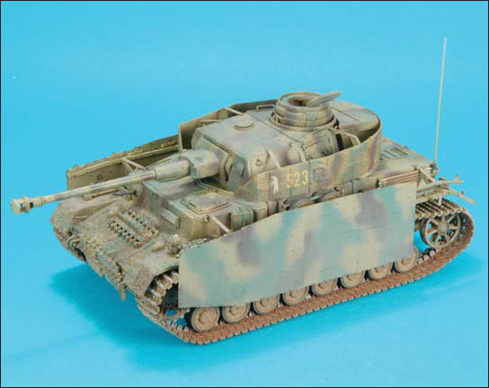
The Pz.Kpfw. IV Ausf. H was produced from May 1943 until February 1944. In June 1943, the frontal armour plates were increased to 80mm thick and the visors on the sides of the superstructure were eliminated. In September 1943, Zimmerit anti-magnetic mine coating was applied at the factories, with some tanks receiving field applications by divisional maintenance companies. Welded dampers for the roadwheels, forged hubcaps, steel return rollers and a cast idler were other modifications introduced in late 1943. In all, 2,322 Pz.Kpfw. IV Ausf. H were completed.
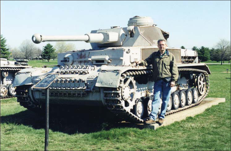
Tom Cockle with the Panzer IV Ausf. G at Aberdeen Proving Ground in April 2003.
The Pz.Kpfw. IV Ausf. J was the last version to be produced, starting in February 1944. Among the changes introduced were the elimination of the visors and pistol ports in the turret side hatches, the welding of three sockets on the turret roof for mounting a 2-ton jib crane, the conversion of the exhaust to a Flammenvernichter version, the elimination of the Zimmerit, the conversion to hull side skirts made from heavy wire mesh instead of steel plates, the installation of a swivelling cupola lid, the extension of the hull sides on the front and rear with holes for towing, and the elimination of one return roller on each side.
Several Pz.Kpfw. IV Ausf. H and Ausf. J were converted or built as Panzerbefehlswagen and Panzerbeobachtungswagen IV, command and artillery spotting vehicles respectively. They can be identified by the placement of an armoured housing on the right rear superstructure to mount the star antenna and the fitting of an extendable rotating periscope in the left side of the turret roof. The Pz.Beob.Wg. IV was also fitted with a commanders cupola taken from the Stug. III Ausf. G.
In my previous book, Osprey Modelling 26: Modelling the Early Panzerkampfwagen IV (Osprey Publishing Ltd: Oxford, 2005), the early-production Panzer IV Ausf. A to Ausf. F mounting the 7.5cm KwK L/24 gun were covered. This book covers the later versions that mounted the 7.5cm KwK 40 L/43 and L/48 gun. The following chapters illustrate some of the techniques, tools and modifications required to construct models of the long-barrel variants of the Panzerkampfwagen IV, and demonstrate some of the available kits and accessories.
Tools and materials
Some of the specialized modelling tools, both commercially produced and homemade, that were used on some of the models constructed for this book are described in the following chapter.
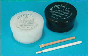
Epoxy putty
Aves Apoxie Sculpt is the two-part epoxy putty that was used to make the Zimmerit on the Panzer IV Ausf. H described in one of the chapters in this book and for weld beads on another. Equal parts of the two components were thoroughly kneaded together before being applied to the model. Special homemade tools were used to create the pattern in the Zimmerit coating and the weld beads.
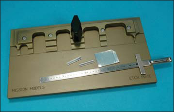
Etched brass folding tool
The Mission Models Etch Mate was used to fold some of the photo-etched brass components used on the models in this book. It is particularly handy for longer pieces, such as the Aber Panzer IV fenders, as the tool is 6.5in. long.
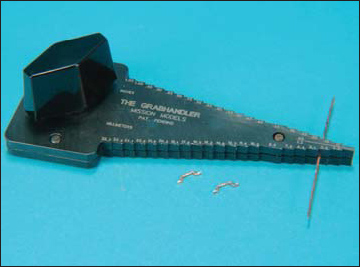
Grab handle bending tool
The Mission Models Grab Handler was used to bend brass and copper wire for some of the engine deck hatch and turret grab handles. The stepped edges are marked in decimals of an inch and millimetres as an aid to help select the correct width to be used.
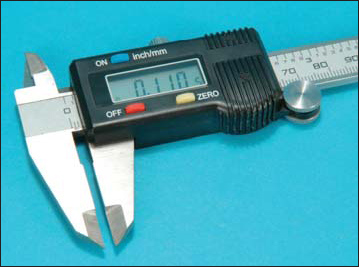
Digital calliper
The digital calliper came in handy when determining which drill bit to select for a specific piece of brass or plastic rod, without having to try one or two drill bits to get the correct size hole. It is also handy for measuring loose bits of styrene from the spares bin when trying to find a specific size.
Screw head tools
A specialized screw head making tool was made from a piece of stainless-steel tubing that had one end sharpened around the outside to produce a ring equal to the inside diameter and around the inside of the other end to produce rings equal to the outside diameter. The tube was chucked into a pin drill and pressed into the surface of the plastic in a rocking motion. The slots were made with a chisel shaped jewellers screwdriver.
Aves Apoxie Sculpt two-part epoxy putty was used to make Zimmerit and weld beads in the construction of some of the models in this book.
The Mission Models Etch Mate photo-etched metal bending tool was used to fold the Aber Panzer IV brass fenders used on two of the models in this book.
The Mission Models Grab Handler was used to bend brass and copper wire for engine deck and turret grab handles.
A digital calliper is a handy tool for accurately measuring the thickness and diameter of styrene strip and rod.

