 Creo Parametric Basic Turning 1/265 Creo Parametric Basic Turning Jouni Ahola ISBN 978-952-7074-32-9 Copyright Jouni Ahola February 2015 Publisher: Klaava Media www.klaava.com All rights reserved. This book may not be reproduced in any form, in whole or in part, without written permission from the author. Creo Parametric Basic Turning 2/265 Table of contents Creo Parametric Basic Turning 3/265 Creo Parametric Basic Turning 4/265 Creo Parametric Basic Turning 5/265 CREO PARAMETRIC INTERFACE 1.1This book This book is a follow-up to the books Creo Parametric Modeling and Creo Para-metric Basic Milling. If you already know the basis of the Creo Parametric and modeling you can use this book easily. If you are using the software first time, and want to go straight to the CAM module, you can download the needed 3D models and tools: The downloaded models are in the native Creo Parametric 2-format (.prt), (.asm), (.drw) and (mfg). The models are also available in the STEP-format.
Before you use Creo Parametric to machine components (CAM), it is important to understand the complete manufacturing process and the steps involved in this pro cess. It is also important to understand the elements that make up completed manu facturing models. Download site: http://www.gold-cam.fi/en/download Or inquire 1.2
Chapters and Tasks
This book consists of several chapters each dealing with a primary theme of Creo Parametric and are meant to be used alongside the running Creo Parametric. You will learn the material best if you take time along the way to read the text
care-fully and
think about what you are doing and observing what happens. Usually, first is the theory and then is the
Task.
Creo Parametric Basic Turning 6/265
1.3Introduction to Turning Manufacturing
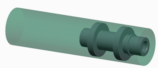
The turning manufacturing process can be divided into different main-level steps;
1. 


 Creo Parametric Basic Turning 6/265 1.3
Introduction to Turning Manufacturing
The turning manufacturing process can be divided into different main-level steps;
1.
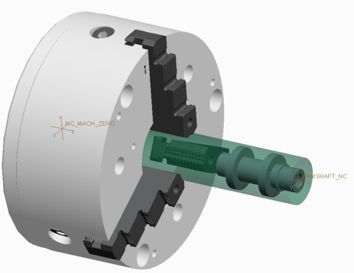
Manufacturing Template2. Reference Model3. Workpiece4. Ref Model and Workpiece5. Fixture6. NC Sequences and tools7.
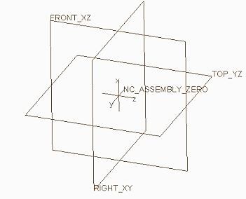
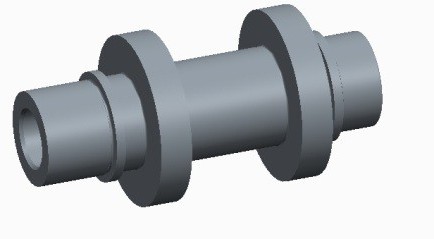
Simulation8. CL Data and Postprocessing CNC Code Creo Parametric Basic Turning 7/265 1. A template manufacturing model can be selected and copied during the creation process. Using template manufacturing models enables you to standardize on the initial manufacturing model configuration. By default, the template manufactur ing model includes default datum planes and a default coordinate system. The reference model represents the final machined component. The reference model represents the final machined component.
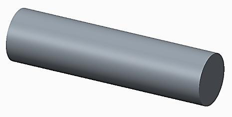
Surfaces and edges are selected from the reference model and are used as references when cre ating NC steps. The reference model can be also imported from the other CAD software. You must assemble a reference model before creating NC steps. 3. Workpiece model This represents the unmachined stock material. It is an op tional element and is not required to create NC steps.
However, using a workpiece enables you to simulate the machining of the stock material. Workpieces can be standard stock billets or you can configure them to represent models such as castings. 4. You can assemble or create a workpiece in a manufacturing model. A number of options are available. 5. Fixtures are parts or assemblies that can be used to hold the component being machined. Fixtures are parts or assemblies that can be used to hold the component being machined.
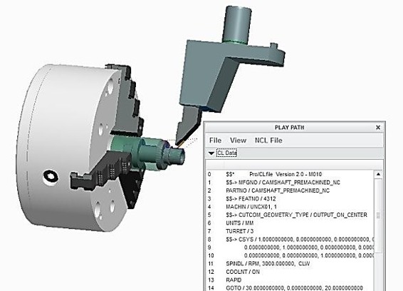
For example, you can create chuck assemblies and use them as fix tures. 6. An NC sequence is a workpiece feature that represents a single tool path. The tool path consists of: Cut motions, that is, tool motions while actually cutting the workpiece material Approach, exit, connect moves Additional CL commands and post-processor words (for example, feedrates, PPRINT, OPSTOP). 7. Toolpaths and machine simulations are one of the most important stages in the manufacturing process.
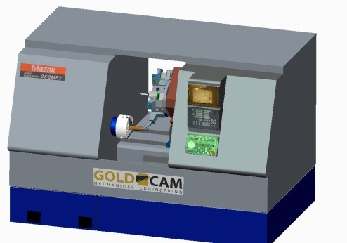
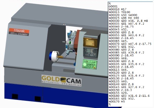
You can display the toolpath for an operation, a single step, or multiple steps. You can also display tool path and machine simulation to gether if the machine assembly is defined. 8. Post-processing is the final stage in the manufacturing process. When toolpaths and simulation have been completed, you can create ASCII format cutter location (CL) data files for operations or selected NC steps. 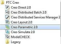
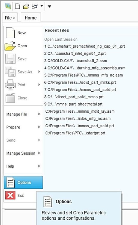
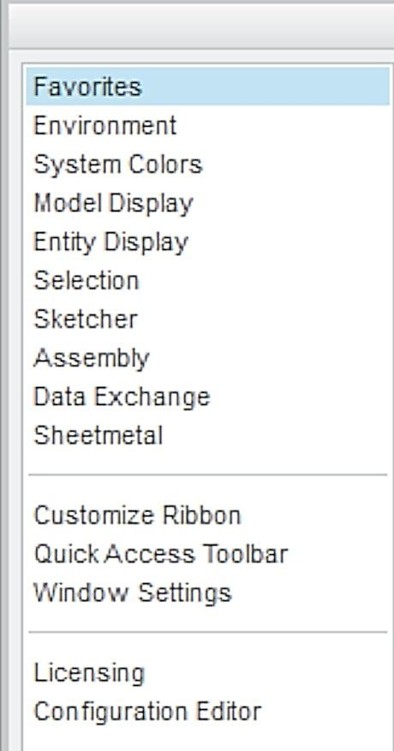
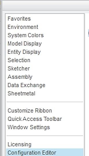
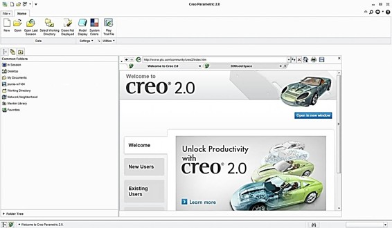 Creo Parametric Basic Turning 8/265 1.4Starting Opening the software: The main interface:
Next page


 Creo Parametric Basic Turning 1/265 Creo Parametric Basic Turning Jouni Ahola ISBN 978-952-7074-32-9 Copyright Jouni Ahola February 2015 Publisher: Klaava Media www.klaava.com All rights reserved. This book may not be reproduced in any form, in whole or in part, without written permission from the author. Creo Parametric Basic Turning 2/265 Table of contents Creo Parametric Basic Turning 3/265 Creo Parametric Basic Turning 4/265 Creo Parametric Basic Turning 5/265 CREO PARAMETRIC INTERFACE 1.1This book This book is a follow-up to the books Creo Parametric Modeling and Creo Para-metric Basic Milling. If you already know the basis of the Creo Parametric and modeling you can use this book easily. If you are using the software first time, and want to go straight to the CAM module, you can download the needed 3D models and tools: The downloaded models are in the native Creo Parametric 2-format (.prt), (.asm), (.drw) and (mfg). The models are also available in the STEP-format.


 Creo Parametric Basic Turning 6/265 1.3
 Creo Parametric Basic Turning 8/265 1.4Starting Opening the software: The main interface:

