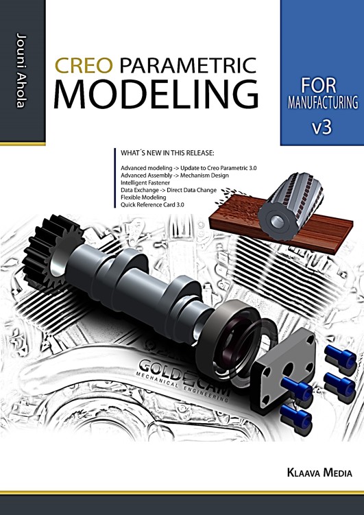
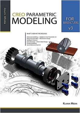
 Creo Parametric Basic Modeling 2/350 Creo Parametric Modeling for Manufacturing Jouni Ahola ISBN 978-952-7074-11-4 Copyright Jouni Ahola February 2015 Publisher: Klaava Media www.klaava.com All rights reserved. This book may not be reproduced in any form, in whole or in part, without written permission from the author. Creo Parametric Basic Modeling 3/350 Table of contents Creo Parametric Basic Modeling 4/350 Creo Parametric Basic Modeling 5/350 Creo Parametric Basic Modeling 6/350
  Creo Parametric Basic Modeling 7/350
INTRODUCTION TO CREO PARAMETRIC
1.1What is Creo Parametric PTC Creo Parametric is the standard in
3D CAD, featuring state-of-the-art productiv ity tools that promote best practices in design while ensuring compliance with your industry and company standards. PTC Creo Parametric provides the broadest range of powerful yet flexible 3D CAD capabilities to help you address your most pressing design challenges including accommodating late stage changes, working with multi CAD data and electromechanical design. A scalable offering of integrated, parametric, 3D CAD, CAID, CAM, and CAE solu tions allows you to design faster than ever, while maximizing innovation and quality to ultimately create exceptional products. As part of the PTC Creo product family, PTC Creo Parametric can share data seam lessly with other PTC Creo apps.
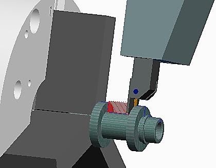
This means that no time is wasted on data transla tion and resulting errors are eliminated. Users can seamlessly move between differ ent modes of modeling and 2D and 3D design data can easily move between apps while retaining design intent. This results in an unprecedented level of interoperabil ity and delivers break-through productivity gains throughout many product devel opment processes. (PTC) 1.2This book The purpose of this book is modeling for manufacturing. It means that the modeled parts are used in the CAM module. The product design is not just based on good de sign but it should be possible to produce by manufacturing as well.
Often an other wise good design is difficult or impossible to produce. Download site: http://www.gold-cam.fi/en/download Or inquire  Creo Parametric Basic Modeling 8/350 1.3
Chapters and Tasks
This book consists of several chapters each dealing with a primary theme of Creo Parametric and are meant to be used alongside the running Creo Parametric. You will learn the material best if you take time along the way to read the text
care-fully and
think about what you are doing and observing what happens. Usually, first is the theory and then is the
Task. Tasks are marked as chapter num bers, for example:
Task 1.3: How to use this book? When the task is ready, there is a text:
Task 1.3 is ready.

Creo Parametric Basic Modeling 9/350
1.4Feature-Based modeling Creo Parametric enables you to create solid model (3D) representations of your part and assembly models.
Solid models: Are realistic visual representation of designs. (CAD) Contain properties such as mass, volume, and center of gravity. Can also be used to check for interferences in an assembly. Can also be used for strength analyses (FEM) Can also be used for manufacturing (CAM) Creo Parametric is a feature-based product development tool. The models are con structed using a series of easy to understand features. The geometric definition of a model is defined by the type of features used and the order in which each feature is placed.
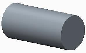
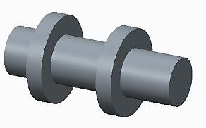
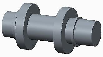
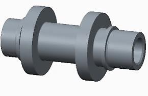
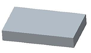
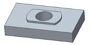
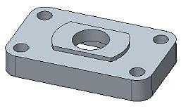
Each feature builds upon the previous feature and can reference any of the preceding features, therefore enabling design intent to be built into the model. With feature-based modeling: You build one simple feature at a time. Each new feature can reference previous features. You can compare 3D-modeling to the real manufacturing: First you have stock plate or round billet and you make cuts, holes, extrusions and rounds and so on to have ready product. 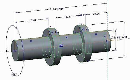
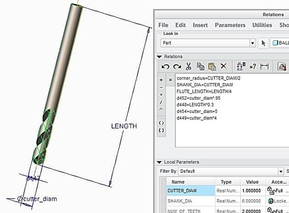
 Creo Parametric Basic Modeling 10/350 The parametric nature and feature-to-feature relationships in Creo Parametric enable you to easily capture design intent and make design changes. Parametric: Model geometry is controlled by parameters and dimensions.
When you modify dimension values, relevant geometry is automatically up dated. Parent/child relationships: Features referenced during creation become parents. If parent features change, child features predictably change accordingly. Creo Parametric models are value-driven, using dimensions and parameters to define the size and location of features within the model. If you edit the value of a feature dimension, that feature updates accordingly. The change then automatically propa gates through to related features in the model and eventually updates the entire part.
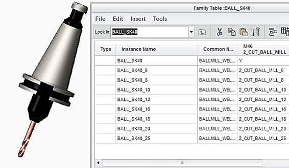
If you want to go a little higher level, you can use parameters in your design. You can make family table parts and assemblies. 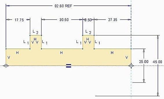
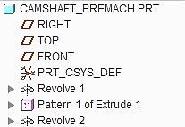
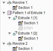 Creo Parametric Basic Modeling 11/350 1.5Creo Parametric Sketcher Geometry Most 3-D geometry created in Creo Parametric begins with a 2-D sketched section. Consequently, sketching is one of the most fundamental, consistently performed op erations. You use the 2-D Sketcher mode to capture your engineering idea. 1.6Creating Internal Sketches When creating sketched features in Creo Parametric, you can use either internal or external sketches.
Next page


 Creo Parametric Basic Modeling 2/350 Creo Parametric Modeling for Manufacturing Jouni Ahola ISBN 978-952-7074-11-4 Copyright Jouni Ahola February 2015 Publisher: Klaava Media www.klaava.com All rights reserved. This book may not be reproduced in any form, in whole or in part, without written permission from the author. Creo Parametric Basic Modeling 3/350 Table of contents Creo Parametric Basic Modeling 4/350 Creo Parametric Basic Modeling 5/350 Creo Parametric Basic Modeling 6/350
  Creo Parametric Basic Modeling 7/350
 Creo Parametric Basic Modeling 8/350 1.3


 Creo Parametric Basic Modeling 9/350 1.4Feature-Based modeling Creo Parametric enables you to create solid model (3D) representations of your part and assembly models.

 Creo Parametric Basic Modeling 10/350 The parametric nature and feature-to-feature relationships in Creo Parametric enable you to easily capture design intent and make design changes. Parametric: Model geometry is controlled by parameters and dimensions.

 Creo Parametric Basic Modeling 11/350 1.5Creo Parametric Sketcher Geometry Most 3-D geometry created in Creo Parametric begins with a 2-D sketched section. Consequently, sketching is one of the most fundamental, consistently performed op erations. You use the 2-D Sketcher mode to capture your engineering idea. 1.6Creating Internal Sketches When creating sketched features in Creo Parametric, you can use either internal or external sketches.