Fundamental electromagnetic, fluid flow, and thermal laws governing the design philosophy of rotating field electric machines are discussed, and the importance of simultaneous consideration of various engineering disciplines thereby is emphasized. The application of basic laws of electromagnetism in electric machines is illustrated with examples of ironair boundary and current imaging. Solutions of the fundamental heat transfer equation for various combinations of electric and thermal parameters are discussed, and electrothermal conductance is introduced. Performance of permanent magnet excitation is analyzed. It is shown that constant magnetization is the Achilles heel of a permanent magnet excited synchronous machine and the main reason for its inferiority to wound rotor synchronous machine. Lumped element parameters in electric, magnetic, thermal, and fluid flow circuits are introduced.
1.1 General Considerations
To design an electric machine means to determine the combination of geometric parameters, winding configuration, and implemented materials, which ensures a flawless operation of the designed machine throughout the whole period of its service life. Considering numerous technical and economical criteria which have to be satisfied in the process of machine design, one comes to a conclusion that there are many ways to design a good machine. On the other hand, there are even more ways to design a machine, the performance of which does not fulfill given specifications, the most pronounced of them being thermal overloading of insulation. The process of electromechanical energy conversion is accompanied with a generation of electromagnetic and mechanical losses in the machines active and passive components. On their way through machine parts the losses create temperature gradients and hot spots , the latter denoting locally overheated areas.
Considering thermal limits of winding insulation, the main criterion that a successfully designed electric machine has to fulfill is that the hot spot temperature in it does not exceed the amount allowed for the given class of insulation. Proper thermal design is crucial for the operation of an electric machine; a thermally poor designed machine must either operate derated, delivering less power than foreseen, or it fails completely because of overheating of its windings.
Losses generated in the whole volume of active part can be transferred to a coolant only on heat exchange surfaces . Considering constant losses per volume and denoting by x the machines linear dimension, the total losses increase with the machine volume, i.e., proportional to x 3, whereas the heat exchange surface can only increase proportionally to x 2. The ratio of total losses to the heat exchange surface, being proportional to the temperature drop on the heat exchange surface, increases proportionally to the machine size, i.e., to the quotient x 3/ x 2 = x . For this simple reason it is easier to cool small than large electric machines. Without changing the machine cooling type, current density in a small induction motor may reach 10 A/mm2; it has, however, to be reduced to some 24 A/mm2 in a large machine with the same class of insulation. Consequently, the importance of cooling increases proportionally to the machine size and dominates design of large electric machines.
The simple scaling law for heating not only is typical for machines but also can be observed in the whole nature. An Antarctic penguin is bigger than an Australian: Considering identical metabolism, body temperature, and produced energy per body volume, an Antarctic penguin can cover a higher temperature difference to its environment than an Australian only by being bigger, i.e., by having a larger volume to body surface area.
1.2 Stationary Coils and Rotating Magnetic Field
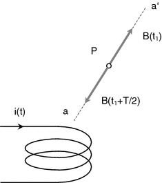
Constant current creates constant magnetic field at each point in space around a current-carrying conductor. Time-dependent current creates time-dependent magnetic field. Considering linear and homogenous magnetic properties of medium surrounding the conductor, the direction of magnetic field at any point in space is determined only by geometry and independent of the amount of current. Time-dependent current creates at every point in a homogenous medium a magnetic field with an amplitude dependent on current and with constant direction in space. In other words, magnetic field around a current-carrying conductor pulsates when the current alternates . One should note that electric current, as a time - dependent quantity, can only alternate, i.e., change its amount in time. Magnetic field, as a spatial quantity, can both change its magnitude and direction in space. As shown in Fig. , the direction of a pulsating magnetic field at point P at time instant t 1, when the current is positive, is collinear with axis a a . After one half of period of current i , at time instant t 1 + T /2 when the current has an opposite sign, the direction of magnetic field changes by 180.
Fig. 1.1
Illustrating the direction of magnetic field at an arbitrary point P at two time instants which are one half of period of current shifted to each other
Sinusoidal current i ( t ) = I max cos t flowing through the coil in Fig..
Fig. 1.2
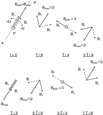
Representation of a pulsating field created by sinusoidal current with angular frequency as a sum of two waves of rotating fields B + and B
The axis of pulsating field B puls acting at point P in Fig.. For a given sinusoidal coil current the amplitude of field B puls changes periodically from 0 over B max down to B max and back to 0. The axis a a of field B puls acting at point P does not change its slope and position in space. The actual field B puls which pulsates along the axis a a can be replaced by a sum of two fields having constant amplitudes B + and B which rotate in opposite directions with angular velocities + and . The relationship between the amplitudes of rotating and pulsating field is B + = B = B max/2. The rotating field component denoted by B + is called positive sequence , and the rotating field component denoted by B is the negative sequence.
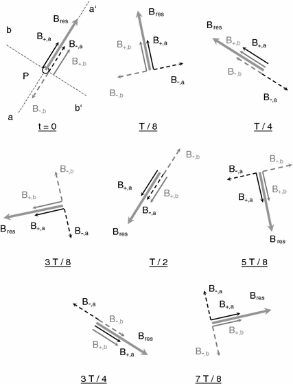
As illustrated in Fig. , in which the magnetic field created by currents in two coils is represented, the lines of flux of which are perpendicular to each other at point P.
Fig. 1.3
Generation of rotating field with two perpendicular coils carrying 90 out of phase alternating currents
The line a a shown in Fig. represents the axis of pulsating field created by the first coil and the line b b analogously for the second coil. For the purpose of simplicity, it will be further assumed that the two amplitudes of magnetic field at point P created by the two currents are equal to each other and that the phase shift between the two coil currents is equal to 90. All components of field created by the current in the first coil are drawn black, and those created by the second coil are gray. The resulting field B res is represented with thick gray arrow.


