How is it possible to use computer simulation to predict the behavior of some process that has not yet happened? How can the aerodynamic properties of an aircraft be computed before it has been built and even without wind tunnel experiments using a model. How can the computer predict the coming change in the weather when it has access solely to the weather data at the current point in time? The weather pattern for tomorrow has never occurred before.
The answer is that there are physical laws that are formulated as mathematical formulas that always hold, even in the future. This is a mathematical model. However, this model is certainly not a formula or graph where, in the case of weather prediction, we can plug in the coordinates of a certain place on earth to obtain the weather parameters such as air pressure, wind velocity etc. at some future point in time. It is rather a set of equations specifying certain relations between different variables. These equations are the fundamental physical laws expressed in mathematical terms. The problem is that these equations require a solution, and they are very difficult to solve. By using two examples, we shall indicate the basic ingredients in the computational process, without going into any details in this introductory chapter. In the last section we shall also give an overview of the content of the rest of the book.
1.1 Computational Example 1
When the Wright brothers constructed the first flying aircraft at the beginning of the 20th century, they were using basic aerodynamic knowledge, but not much quantitative computation. They were using the basic principle for flying: the wings are given a shape such that the air is flowing faster on the upper surface compared to the lower one, resulting in thinner air with lower pressure on top of the wing. If the difference between the pressure above and below is large enough, the resulting lifting force overcomes the gravitational pull downwards, such that the aircraft can lift off the ground and keep itself flying.
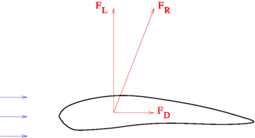
The situation is illustrated schematically in Fig. showing a section through the wing called an airfoil . For practical reasons it is easier to consider the airfoil at rest with the air blowing from the left at the same speed as the aircraft is flying. The air is creating a force F R acting upon it. This force can be split into one component F D directed against the flight direction and one component F L pointing upwards. The latter has to be larger than the gravitational pull that is trying to get the aircraft down. If the wing has the right geometry, and the engine is powerful enough, the lifting force becomes sufficiently large.
Fig. 1.1
Lift and drag forces on an airfoil
The question is now how to design the airfoil such that F L becomes as large as possible, while at the same time F D is kept as small as possible. Here is where the mathematical model is needed. The most convenient situation would be if the forces could be computed directly as explicit formulas, where the constant aircraft speed v 0 is a given parameter. This means that for a given geometry of the airfoil, the formulas could be written as
where f L ( v 0) and f D ( v 0) are certain mathematical expressions that can be evaluated for any given value of v 0. Complicated expressions dont create any problems, since we have computers that can do the computations easily and quickly. But the unfortunate fact is that no such formulas exist. No matter how complicated we allow them to be, as long as they consist of a series of elementary algebraic expressions and functions, they are not to be found.
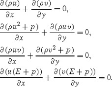
It seems that we are stuck with an impossible situation. We have very large and fast computers at our disposal, and still we have no formulas to feed them for evaluation. But there is a way out. We can derive a mathematical model that doesnt have the simple explicit form that we would like, but is still the basis for further operations that finally lead to an approximate solution. In aerodynamics such models were derived long ago. They are based on the very early fundamental work by Isaac Newton (16431727) and Leonhard Euler (17071783). For an aircraft at a constant speed, a simplified model is a system of equations
These are the Euler equations , where it is assumed that the air has no viscosity. Furthermore we have assumed that there is no variation in the z -direction. These equations have a simple and, for a mathematician, nice-looking structure, but they are difficult to solve. Actually, it is impossible to solve them exactly. Let us first see what the various symbols stand for.
A standard Cartesian coordinate system has been introduced with x and y as the coordinates in space. The state variables representing physical quantities are
density,
u
velocity component in x -direction,
v
velocity component in y -direction,
E
total energy per unit volume,
There are five state variables but only four equations. Therefore we need one more equation
This is the equation of state, which is such that, for any given value of the variables within the parenthesis, the pressure p can be easily evaluated. The symbol represents the differential operator , and it stands for the rate of change of a variable. The expression ( u )/ x is called the derivative of u with respect to x , and it tells how the quantity u changes in the x -direction. Each equation states the connection between changes of certain variables in different directions. The first equation tells us that the changes of u in the x -direction and v in the y -direction cancel each other. This is called the continuity equation , and it is a way of expressing the basic physical fact that no material is created or destroyed.

