1.1 Introduction
An operational amplifier is a direct current (DC) amplifier intended for executing (together with external elements) various operations on (above) input signals and capable of working with the large feedback.
This term arose in the 1930s [ and initially it applied to DC amplifiers used in telephony and analog computers.
First operational amplifiers (op-amps) were based on electronic tubes; they executed linear mathematical operations with input voltages: multiplication by a constant, differentiation, and integration, and allowed electronic modeling of differential equations. These op-amps had large size and several supply voltages and consumed power up to several watts.
With further development of semiconductor industry, hybrid op-amps (assembled of separate elements: transistors and resistors) were designed, and later on op-amps were manufactured on a single piece of silicon crystal (chip). Specifications and characteristics of these op-amps are persistently improved. Now such op-amps are called integral operational amplifiers. Though their basic application has changed since appearance of digital computers, these amplifiers are still referred to as operational and widely used in various electronic devices. This term no longer carries the meaning that had at the beginning. The word operational assumes some operation on signal, but an operational amplifier itself performs no other operations without external elements, but only signal amplification, which is its main and, perhaps, sole function. Modern op-amps perfectly carried out this function.
Op-amps are characterized by the high gain (1,000,000 and more), low input offset voltage (from 0,1 V), wide frequency band (up to 2,000 MHz), and high slew rate (up to 3,000 V/s) [ ]. These op-amp parameters are continuously improving.
Nowadays the industry produces a large number (several hundreds) of various op-amps; therefore, even simple enumeration of their parameters and characteristics, in particular, those that earlier believed atypical for op-amps (for example, low input or output resistance) is a certain problem. It is difficult to orient oneself in this abundance of types and parameters without the necessary structured knowledge about them.
Thus, consideration of op-amps starts with their electrical models, rather than parameters and features of circuitry and production technologies (these issues are sufficiently addressed in the literature). It is assumed that the students already have the basic knowledge about the input and output parameters of op-amps (parameters and characteristics of some of them are presented in Appendix 1).
1.2 Application of Operational Amplifiers
Op-amps are now used in the systems for data acquisition and signal processing of measurement information, entering of the analog signals into the computer, in audio and medical systems, etc. [ ]
They are characterized by small size, wide range of power supply voltages, low consumed power, and others. Besides, they are suitable for any operating conditions. However, the main reason for wide application of op-amps is that the parameters and characteristics of a device are independent of the parameters and characteristics of the op-amp itself, because, as known, the op-amp parameters are usually instable in time and vary with temperature and frequency, and so developers of electron devices try all ways to minimize their effect. A large feedback allows reaching it. The needed functions of a device are rather readily achieved in this case using of external elements.
The relative easiness of designing various circuits with op-amps caused a simplified attitude to them. Now the knowledge of parameters and characteristics of operational amplifiers sometimes substitutes for the recognition of their structure. The common opinion is that for application of op-amps it is not needed (rather, not necessarily needed) to know their circuit, but it is sufficient to be aware of the input and output (interface) characteristics and to consider the op-amp itself as a black box. This statement applies not only to amplifiers. Thus, most of computer manufacturers scarcely know the principle circuit of the Pentium microprocessor, and this does not hinder them to create excellent computers. Op-amps are considered as such circuit elements, for example, resistor or capacitor, with only somewhat more complex internal structure. Moreover, the wide usage of software for modeling electronic devices on personal computers (Multisim, Electronics Workbench, DesignLab, Orcad, Protel, and others) approves this approach, because op-amps in such a case are selected from a library, as any other element. Nevertheless, the system modeling assuming the knowledge of the structure, structural relations, and principles of construction of various operational amplifiers allows one to more competently design and operate electron devices based on them. This concept can be supported by the following.
First, any op-amp model is certainly more simple than the principle circuit and, even more so, its physical prototype.
Second, from the system point of view, the amplifier scheme corresponds to a higher level of modeling, including any model of a black box with all its parameters.
Third, the knowledge of the internal structure allows one to more efficiently apply op-amps and to use methods for correction of their characteristics, in particular, those not documented by the manufacturer.
Finally, alphanumeric indexes of operational amplifiers give no information about their structure (for example, 140UD1 and 1401UD1 (Russian) amplifiers have absolutely different structures and different applications).
Op-amps have widely different designs, parameters, and characteristics, and the main problem for developer is to find the best op-amp for some device or another one, because the correct and reasonable choice of an op-amp determines the cost, reliability, and quality of the device under development.
All amplifiers can be divided into two groups: amplifiers with potential (high resistance) input and amplifiers with current (low resistance) input. Let us consider these two types.
1.3 Amplifiers with Potential Input
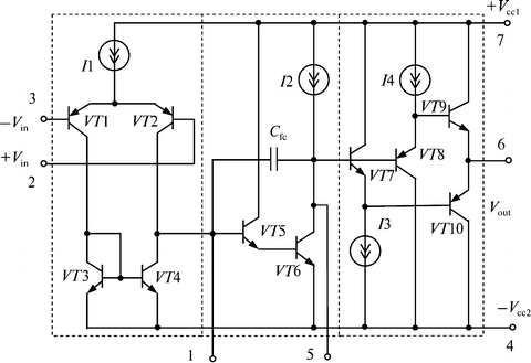
The circuit of the K157UD4 op-amp with potential input made using the bipolar technology is shown on Fig. ] includes three amplifier stages.
Fig. 1.1
Circuit of K157UD4-type op-amp with the VCVS structure
The first (input) stage is a symmetric differential one; it is constructed in VT 1 VT 4 transistors. The input signal is given to one of the bases of the VT 1 and VT 2 transistors or to the both bases simultaneously. The signal amplified by the first stage comes to the second (intermediate) stage constructed in VT 5 and VT 6 transistors, and after amplification by the second stage it comes to the third (output) stage designed in VT 7 VT 10 transistors. The output stage is connected in the circuit of a push-pull compound emitter follower constructed in VT 8, VT 9 and VT 7, VT 10 complementary transistors, respectively. Note that each arm of the stage includes the current sources I 3 and I 4. Current sources are usually represented by transistors, and for their normal operation the voltage drop no less than 11.5 V is needed. Consequently, the output voltage of the amplifier is always lower than the supply voltage by 1.52 V.
