Measurement of Mobile Robots with Arduino LM393 Sensors
COMPONENTS AND SUPPLIES
|
| Arduino UNO |
|
| Texas Instruments LM393 chip |
NECESSARY TOOLS AND MACHINES
APPS AND ONLINE SERVICES
ABOUT THIS PROJECT
LM393 Speed Sensor Module (H206)
Before we start the project's circuit diagram and code, let us understand the LM393 speed sensor module, because it plays a vital role in the project. H206 speed sensor module is composed of infrared light sensor and LM393 voltage comparator IC, so it is named as LM393 speed sensor. The module also includes a grid plate, which must be mounted on the rotating shaft of the motor. All components are marked in the image below.
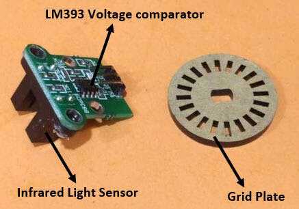
The infrared light sensor is composed of infrared LED and phototransistor, separated by a small gap. As shown above, the entire sensor device is placed in a black housing. The grid plate is composed of grooves, and the plate is arranged between the gaps of the infrared light sensors so that the sensor can sense the gap in the grid plate. Each gap in the grid plate triggers the IR sensor when passing through the gap; a comparator is then used to convert these triggers into a voltage signal. The comparator uses ON Semiconductor's LM393 IC. The module has three pins, two of which are used to power the module, and one output pin is used to count the number of triggers.
H206 Sensor Installation
Installing these types of sensors is a bit tricky. It can only be installed on motors with shaft protruding on both sides. One side of the axle is connected to the wheel, while the other side is used to install the grid, as shown above.
Since the wheels and wheels are connected on the same axis, both rotate at the same speed, so by measuring the vehicle speed, we can measure the speed of the wheels. Make sure that the gap in the grid plate passes through the infrared sensor before the sensor can count the number of gaps that pass through. As long as the specified conditions are met, you can also set up your own mechanical device to install the sensor. Infrared sensors are commonly used in many robot projects to guide robots to understand obstacles.
The grid plate shown above has 20 slots (grids). This means that the sensor will find 20 gaps for one full rotation of the wheel. By calculating the number of gaps detected by the sensor, we can calculate the distance traveled by the wheel, and similarly by measuring the speed of the gap found by the sensor, we can detect the speed of the wheel. In our robot, we install this sensor on two wheels, so we can also find the angle of the robot. However, using an accelerometer or gyroscope can calculate the rotation angle more wisely. Here we learn to use the Arduino to interface the accelerometer with the gyroscope and try to use them to measure the rotation angle.
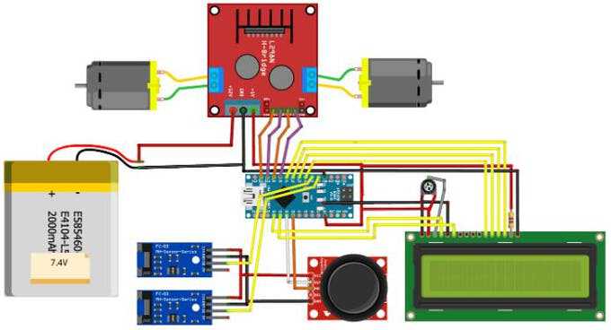
Schematic
The complete circuit diagram of the speed and distance sensing robot is shown below. The robot uses the Arduino Nano as its brain, and the two DC motors for the wheels are driven by the L298N H-bridge motor driver module. The joystick is used to control the speed and direction of the robot, and the two speed sensors H206 are used to measure the speed, distance and angle of the robot. Then, the measured value is displayed in the 1602 LCD module. The potentiometer connected to the LCD can be used to adjust the contrast of the LCD, and the resistor is used to limit the current flowing to the LCD backlight.
The entire circuit is powered by a 7.4V lithium battery. The 7.4V power supply is provided to the 12V pin of the motor driver module. The voltage regulator on the motor driver module then converts 7.4V to a regulated voltage + 5V for powering the Arduino, LCD, sensors and joystick.
The motor is controlled by Arduino digital pins 8, 9, 10 and 11. Since the speed of the motor must also be controlled, we should provide a PWM signal to the positive pole of the motor. Therefore, we have pins 9 and 10, which are both PWM pins. The X and Y values of the joystick are read using analog pins A2 and A3, respectively.
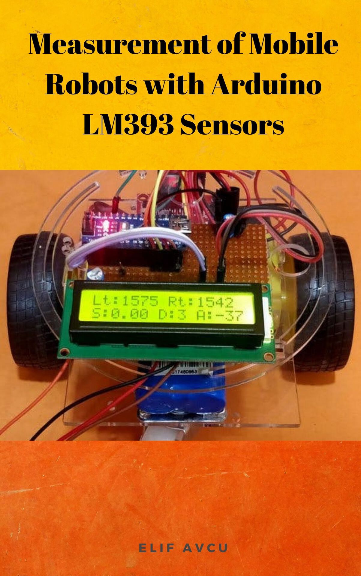
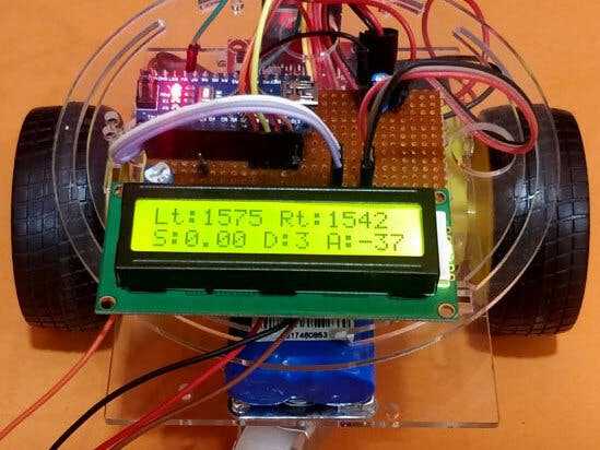
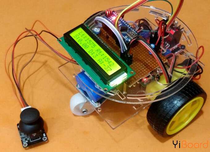
We know that the H206 sensor triggers when it detects gaps in the grid. Since these triggers cannot always be accurately read to calculate the correct speed and distance, the trigger (output) pins are connected to external interrupt pins 2 and 3 of the Arduino board. Assemble the entire circuit on the chassis and install the speed sensor according to the instructions. After the connection is completed, the robot will look like the following.
The hardware part has been completed. let's dive into how to measure the speed, distance and angle of the robot, and then enter the programming part.
The logic behind measuring speed with the H206 sensor
From the sensor installation settings, you should know that the H206 sensor only measures the gaps present in the grid. When installing, ensure that the wheels (whose speed should be measured) and the baffle rotate at the same speed. Just like here, since we install the wheels and wheels on the same shaft, they will all rotate at the same speed.
In our setup, we installed two sensors for each wheel to measure the angle of the robot. But if your goal is to measure only speed and distance, we can install the sensor on any wheel. The output of the sensor (trigger signal) is most often connected to the external interrupt pin of the microcontroller. Each time a gap in the grid is detected, an interrupt is triggered and the code in the ISR (Interrupt Service Routine) is executed. If we can calculate the time interval between two such triggers, we can calculate the speed of the wheel.
In Arduino, we can easily calculate this time interval using the millis () function. Since the device is powered on, this millisecond function will increase by 1 every millisecond. Therefore, when the first interrupt occurs, we can save the value of millis () in a dummy variable (such as pevtime in the code), and then when the second interrupt occurs, we can calculate to subtract from millis () The time required for the pevtime value.