Abraham - Case based echocardiography: fundamentals and clinical practice
Here you can read online Abraham - Case based echocardiography: fundamentals and clinical practice full text of the book (entire story) in english for free. Download pdf and epub, get meaning, cover and reviews about this ebook. City: London, year: 2011, publisher: Springer London, genre: Home and family. Description of the work, (preface) as well as reviews are available. Best literature library LitArk.com created for fans of good reading and offers a wide selection of genres:
Choose a favorite category and find really read worthwhile books. Enjoy immersion in the world of imagination, feel the emotions of the characters or learn something new for yourself, make an fascinating discovery.
Book:
Case based echocardiography: fundamentals and clinical practice
Case based echocardiography: fundamentals and clinical practice: summary, description and annotation
We offer to read an annotation, description, summary or preface (depends on what the author of the book "Case based echocardiography: fundamentals and clinical practice" wrote himself). If you haven't found the necessary information about the book — write in the comments, we will try to find it.
Abraham: author's other books
Who wrote Case based echocardiography: fundamentals and clinical practice? Find out the surname, the name of the author of the book and a list of all author's works by series.
Case based echocardiography: fundamentals and clinical practice — read online for free the complete book (whole text) full work
Below is the text of the book, divided by pages. System saving the place of the last page read, allows you to conveniently read the book "Case based echocardiography: fundamentals and clinical practice" online for free, without having to search again every time where you left off. Put a bookmark, and you can go to the page where you finished reading at any time.
Theodore Abraham (ed.) Case Based Echocardiography 10.1007/978-1-84996-151-6_1
1. Physics and Artifacts
Kenneth D. Horton 1
(1)
Echo/Vascular Laboratory, Intermountain Medical Center, Murray, UT, USA
Kenneth D. Horton
Email:
Fig. 1.1
Definition of sound and ultrasound. Sound is a mechanical vibration that consists of compressions and rarefactions . Sound waves propagate (travel) through various mediums by interactions between the particles that comprise the medium. Therefore, sound cannot travel through a vacuum. The range of hearing in the human ear is 2020,000 Hz. Sound above 20,000 Hz is called ultrasound
Fig. 1.2
Wave terminology. The combination of one compression and one rarefaction is called one cycle . The number of cycles completed in 1 s is called the frequency . The frequency is measured in units of Hertz or, for ultrasound, megahertz (one million cycles/s). The distance occupied by one cycle is called the wavelength and the amount of time occupied by one cycle is the period . The strength of the ultrasound signal is the intensity. The higher the amplitude , the greater the intensity of the ultrasound signal
Fig. 1.3
Interactions with tissue. As a sound wave strikes, a difference in the medium ( acoustic interface ) it is traveling through, some of the sound is reflected back to the transducer ( reflection ) and some continues to travel through the next medium ( refraction ). As the sound wave travels through a medium, it loses its strength or intensity. This is called attenuation
Fig. 1.4
Transducers. A transducer is a device that changes types of energy. An ultrasound transducer has multiple piezioelectric crystals (elements) that can change electrical energy to mechanical energy or vice versa. The crystal is surrounded by a dampening material that prevents ringing when the crystal is activated. The matching layer has an acoustic impendence between that of the transducer and skin and facilitates the transmission of sound into the body
Fig. 1.5
Beam characteristics. In an unfocused transducer, sound leaves the transducer, travels parallel for a period of time and then begins to diverge. The area prior to the divergence is called the near zone and the area after the divergence is called the far zone . Using electronic timing or an acoustic lens, the beam can be focused . The resolution is highest in the area of the focal zone . Ultrasound systems have the ability to move the focal zone along the beam to improve the resolution in areas of interest
Fig. 1.6
Resolution. Resolution is the ability to see two different objects in the imaging field as two different objects and is measured in unit of distance (millimeters). There are multiple types of resolution in ultrasound. The two most common are ( a ) longitudinal resolution resolution along the axis parallel to the direction of the sound propagation and ( b ) axial resolution resolution on the axis perpendicular to the direction of the sound propagation
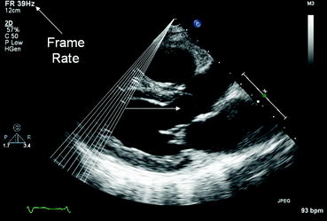
Fig. 1.7
Frame rate. An ultrasound image is created one scan line at a time. When the scan lines are processed across the field of view (sector) one frame is created. The number of frame that is created in 1 s is called the frame rate and is measured in Hertz. The temporal resolution of a system is determined by the frame rate. The higher the frame rate, the better the temporal resolution. In 2D echocardiography, you should attempt to image at the highest frame rate possible
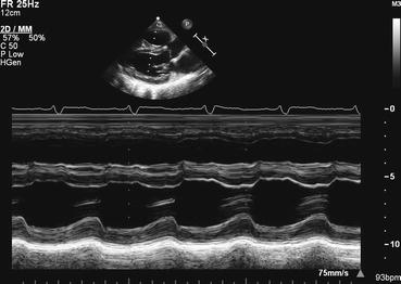
Fig. 1.8
M-mode echocardiography. M-mode (motion-mode) echocardiography is a graphical depiction of the ultrasound signal along a single scan line. The temporal resolution of an M-mode tracing is superior to all other echocardiographic modes because the image is only processing the signal from a single scan line and can be updated thousands of times per second
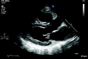
Fig. 1.9
2D Echocardiography. 2D echocardiography is a 2D depiction of the heart. It is usually acquired as a moving picture allowing for assessment of the heart throughout systole and diastole. 2D images are either captured on video tape or as digital loops
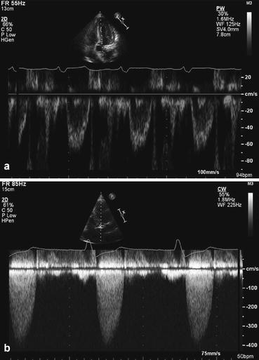
Fig. 1.10
Doppler echocardiography. As its name implies, Doppler images are created using the Doppler effect. Spectral Doppler tracings can be created using either continuous wave (CW) Doppler or pulsed wave (PW) Doppler. CW and PW Doppler each have distinct advantages and disadvantages that determine when each is used. ( a ) PW Doppler has the advantage of range resolution, or being able to measure flow of a specific point. Its main disadvantage is there is a limit to how high of a velocity it can measure (Nyquist limit). ( b ) CW Doppler has an unlimited Nyquist limit and therefore can measure very high velocities. Its disadvantage, however, is it does not have range resolution and measures all flows along the cursor
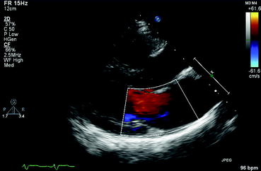
Fig. 1.11
Color flow imaging. Color flow imaging is used to detect the direction and velocity of blood flow. Flow is measured at thousands of points within the color flow sector. By convention, flow toward the transducer is colored red-yellow and flow away from the transducer is colored blue-white . Low flow velocities begin with darker shades and the shade increases as flow velocity increases
Fig. 1.12
3D echocardiography. 3D images are obtained using a pyramidal volume of pixels (voxels). Once the image is obtained, it can be rotated and cropped to better visualize any structure within the image. In this example, a mitral annular ring was placed. ( a ) Assessment of the annular ring from the LA perspective (looking down into the LV) and ( b ) assessment from the LV perspective (looking up into the atrium). Both images were obtained in the same acquisition
Similar books «Case based echocardiography: fundamentals and clinical practice»
Look at similar books to Case based echocardiography: fundamentals and clinical practice. We have selected literature similar in name and meaning in the hope of providing readers with more options to find new, interesting, not yet read works.
Reviews about «Case based echocardiography: fundamentals and clinical practice»
Discussion, reviews of the book Case based echocardiography: fundamentals and clinical practice and just readers' own opinions. Leave your comments, write what you think about the work, its meaning or the main characters. Specify what exactly you liked and what you didn't like, and why you think so.