U.S. Springfield
Model 1922 M2
Similar/Identical Pattern Guns
The same basic assembly/disassembly steps for the U.S. Springfield Model 1922 M2 also apply to the following gun:
U.S. Springfield Model 1922 M1
| Data: | U.S. Springfield Model 1922 M2 |
| Origin: | United States |
| Manufacturer: | Springfield Armory |
| Cartridge: | 22 Long Rifle |
| Magazine capacity: | 10 rounds |
| Overall length: | 43.7 inches |
| Barrel length: | 24 inches |
| Weight: | 8.90 pounds |

The Model 1922 M2 was the final version of a target rifle designed and made at Springfield Armory and used initially for military marksmanship training. A number of these guns were later furnished to educational institutions and sold to NRA members in cooperation with the DCM. The original 1922 rifle was modified to produce the 1922 M1 and 1922 M2 guns, and the earlier guns were usually changed by the Armory as they came in for repair. The earlier guns are different mechanically, especially in the bolt assembly. The final M2 version is the one covered here.
Disassembly:
Remove the magazine. Set the bolt stop lever, located at the left rear of the receiver, on its central position, just a few degrees above horizontal. Withdraw the bolt toward the rear.
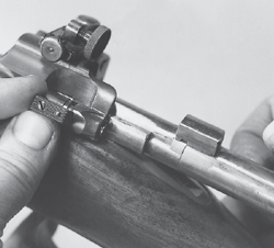
Drift out the cross pin in the stock, just forward of the barrel band.
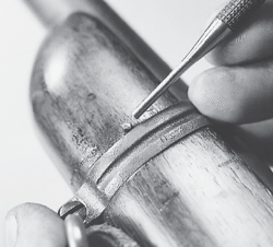
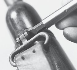
Remove the cross-screw at the bottom of the barrel band and take off the sling loop downward. The band can now be moved off toward the front.
Use a drift punch tip to depress the magazine floorplate latch, accessible in a hole at the rear of the plate. While holding the catch in, move the plate toward the rear; then take it off downward.
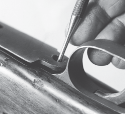
Remove the vertical screw on the underside at the front of the trigger guard unit. Remove the vertical screw on the underside at the rear of the trigger guard and separate the action from the stock. The trigger guard unit can now be taken off downward. The floorplate latch and its spring are retained on the inside of the guard unit by a cross pin and are removed upward.
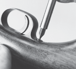
To remove the rear sight, first turn out the knurled knob on the right side at the front of the sight until it stops; then push it toward the rear and hold it there while sliding the sight upward out of its base. It can be taken completely off, or just moved until it exposes the screw covered by the sight slide, near the scale marker.
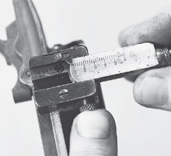
Remove both of the mounting screws, the short one inside the slide track, and the longer one in the forward portion of the sight, and take off the sight base toward the right. Further disassembly of the rear sight is not recommended in normal takedown.
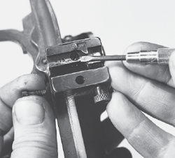
The magazine catch is tempered to be its own spring, and is mounted on the underside of the receiver by two forward side projections which are slid into recesses on each side. To remove it, use a small screwdriver to very slightly lift its rear tail, to clear the locking dimple from its recess, and place a drift punch against the end of the slot in the front of its base, next to the receiver. Tap the unit toward the rear until its side projections clear their slots in the receiver, and remove the magazine catch. Caution:Apply pressureonly to the mounting base plate, and not to the lower extension of the catch, or it may be deformed or broken.
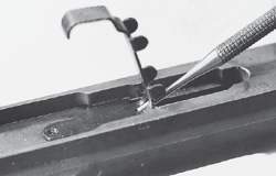
Push out the sear pivot pin toward the left, the side on which it has a large, nail-like head.
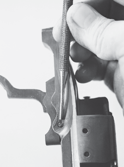
Remove the sear and the attached trigger downward, along with the coil spring mounted in the front of the sear. Drifting out the cross pin in the sear will allow separation of the trigger from the sear.
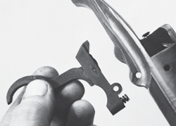
To remove the bolt stop, first back out the small screw in the serrated outer edge of the stop lever. After the screw is removed, withdraw the bolt stop pin toward the rear, using a fingernail or tool in the cannelure provided at its rear tip. During this operation, have the bolt stop turned up to the locked position, and exert slight downward pressure on it to restrain the plunger and spring mounted inside the stop lever. When the pin is out, the bolt stop can be taken off toward the left. Take care not to lose the small spring and plunger.
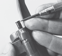
Grip the bolt firmly and pull back the striker knob until the safety can be turned up to vertical position, halfway between the on-safe and off-safe positions. This is more easily done before taking the bolt out of the receiver. Press the bolt sleeve lock inward, hold it in, and turn the rear section of the bolt counterclockwise (rear view), unscrewing the rear portion from the bolt body.
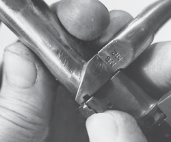
When the middle lug on the bolt body has turned sufficiently to clear the lug on the bolt head from its internal recess, the bolt head can be taken off toward the front.
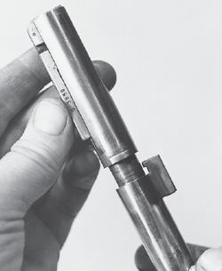
Continue turning the rear section until its threads clear the bolt body, and withdraw the rear assembly from the body of the bolt. During this operation, take care not to disturb the safety-lever, as it is holding the lower lug of the cocking piece out of engagement with the rear of the bolt body.

